Halbach Array Engineering LogoHalbach Array
Start inquiry
Halbach Array Engineering LogoHalbach Array
WhatsApp
Halbach Array Engineering LogoHalbach Array

China-based Halbach array OEM supplier supporting FEA simulation, precision assembly, and global delivery.

Engineering RFQ Inbox

[email protected]

Email RFQ Desk

Include target torque/speed, quantity, and delivery location.

Direct Engineer Chat

+8618857971991

Chat on WhatsApp

Use for drawing, specification, and RFQ clarification.

Products
  • Product Portfolio
  • Linear Halbach Arrays
  • Planar Halbach Arrays
  • Halbach Cylinders
  • Halbach Rings
  • Halbach Rotors
  • Magnetic Couplings
  • Magnetic Gears
  • Maglev Track Arrays
  • Undulator & Wiggler Magnets
  • Custom Assemblies
Applications
  • Application Matrix
  • Linear Motors
  • BLDC Motors
  • Maglev Systems
  • Magnetic Bearings
  • Flywheel Storage
  • NMR & MRI
  • Voice Coil Actuators
  • Eddy Current Brakes
  • Robotics & Actuators
Engineering & Quality
  • OEM Capabilities
  • FEA Simulation
  • Quality & Inspection
  • Precision Assembly
  • Magnetic Materials
  • Export Compliance
  • About Us
  • Contact / RFQ
Resources & Legal
  • Engineering Blog
  • Privacy Policy
  • Cookie Policy
  • Terms of Service
© 2026 Halbach Array. All Rights Reserved.|Halbach Array is operated by Linkup Ai Co., Ltd. with Linkup Precision magnetic assembly resources.|Project quality files available by agreed scope
← Back to Products

Planar Halbach Arrays

2D flat array panels for high-force surface applications.

Target Buyer:Manufacturing equipment designers and automation engineers.
Single-sided planar Halbach magnet array with precision grid layout

Best-Fit Procurement Use

Best fit when the buyer needs high field concentration over a defined work face while protecting electronics, carriers, or mounting hardware behind the array.

Send RFQRequest FEA Review

Capability Highlights

  • High flux concentration on one face
  • Reduced magnetic leakage on the back
  • Customizable pole grid layouts

Typical Applications

  • Magnetic fixtures
  • Planar motors
  • Semiconductor wafer handling

Engineering Focus

  • Surface flatness and mechanical rigidity
  • Grid spacing tolerances
  • Corrosion protection
  • Back-side leakage control near sensors and electronics

Buyer Decision Criteria

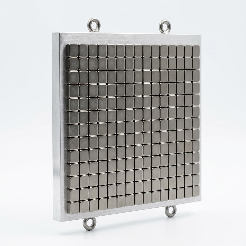
  • Active area, grid pitch, and required working height above the surface.
  • Back-face leakage limit for nearby sensors, PCBs, or fixtures.
  • Flatness, parallelism, and mounting datum control for large plates.
  • Coating and sealing needs for cleanroom, humidity, or chemical exposure.

Factory Capability

  • 2D grid assembly with orientation checks before final potting.
  • Rigid non-magnetic backing plates to control plate warpage.
  • Epoxy, NiCuNi, or Parylene coating selection by environment.
  • Custom hole, slot, and datum machining for OEM integration.

Key Evaluation Matrix

MetricTypical RangeWhy It Matters
Back-face Leakage< 5%Protects sensitive electronics mounted behind the array.
Active Face FlatnessProject-specific by panel size and mounting datumFlatness controls air-gap consistency for planar motors, fixtures, and wafer-handling tools.
Holding Force / Working HeightValidated at the specified distance above the active faceBuyers need force at their real operating height, not a generic pull value at contact.

RFQ Checklist

  1. Area dimensions (L x W)
  2. Grid layout requirements
  3. Desired holding force / field strength
  4. Working height, back-side leakage limit, mounting holes, and coating needs

Risk Controls

  • Warping during assembly: Use of rigid non-magnetic backing plates (e.g., thick Aluminum or Stainless Steel).
  • Unexpected magnetic leakage into nearby electronics: Add back-face leakage checks and adjust magnet thickness, carrier, or shielding where needed.
  • Grid orientation error: Use orientation marking, pre-bonding checks, and 2D field mapping before shipment.

Validation Deliverables

  • 2D surface field map with working height notes.
  • Back-side leakage measurement where required.
  • Flatness and critical dimension inspection.
  • Coating and sealing process notes for approved samples.

RFQ to Delivery Flow

  1. Send active area, grid pitch, working height, mounting pattern, and leakage limits.
  2. We check whether the target field requires grade, thickness, or layout changes.
  3. Prototype plates are measured for flatness and magnetic output before approval.
  4. Production fixtures lock grid orientation and datum references for repeat orders.

Product Gallery

Planar Halbach array fixture
Planar Halbach magnetic plate
One-sided flux Halbach levitation plate
Planar Halbach array isometric engineering illustration
Planar Halbach array top-view pole grid

Buyer FAQ

Are custom grid sizes available?

Yes, we can CNC machine magnets to any specific dimension to match your required pole grid.

Can you validate field strength above the plate surface?

Yes. The useful measurement point is normally the working height above the active face, and it can be included in the inspection plan.

Which carrier materials are common for planar arrays?

Aluminum, stainless steel, and non-magnetic composite carriers are common; the best choice depends on stiffness, corrosion, mass, and mounting needs.

Related Resources

  • Planar motor and wafer handling applications
  • Custom Halbach assemblies
  • FEA and magnetic simulation support
  • Quality inspection and 3D Gauss mapping
  • Precision assembly and bonding controls
  • Send CAD and RFQ details

Engineering RFQ Inbox

[email protected]

Email RFQ Desk

Include target torque/speed, quantity, and delivery location.

Direct Engineer Chat

+8618857971991

Chat on WhatsApp

Use for drawing, specification, and RFQ clarification.