← Back to Products

Linear Halbach Arrays

High force-density magnetic arrays for linear motors and precision stages.

Target Buyer:Engineers designing high-speed, direct-drive linear motion systems.
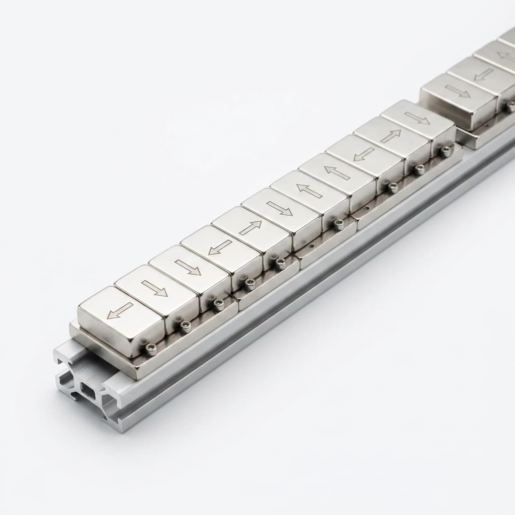
Modular linear Halbach array with NdFeB magnets on aluminum extrusion rail

Best-Fit Procurement Use

Best fit for teams that already know the stroke, pole pitch, working gap, and target thrust profile, and need a factory-side partner to turn those constraints into repeatable magnet track modules.

Capability Highlights

  • One-sided magnetic flux concentration
  • Low ripple force by design target
  • Modular block designs

Typical Applications

  • Linear motors
  • Maglev tracks
  • Precision actuators

Engineering Focus

  • Field uniformity over stroke
  • Minimizing cogging force
  • Thermal stability under high load
  • Module-to-module pitch matching for long travel axes

Buyer Decision Criteria

  • Pole pitch, total track length, and segment-to-segment pitch error.
  • Peak working-side flux density at the real air gap, not only at the magnet surface.
  • Carrier material, mounting pattern, and stiffness requirement for long tracks.
  • Thermal grade selection for continuous duty linear motor operation.
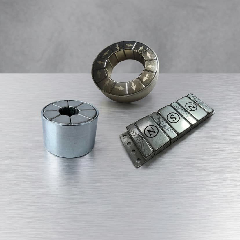
Factory Capability

  • Segmented magnet sorting before assembly to reduce ripple and field deviation.
  • Non-magnetic aluminum or stainless carriers with CNC datum control.
  • Bonding fixtures that hold repulsive blocks during cure without shifting pitch.
  • Modular packaging for long rails shipped as matched sections.

Key Evaluation Matrix

MetricTypical RangeWhy It Matters
Flux Density (Surface)0.8T - 1.2TDetermines the thrust force multiplier in linear motors.
Pole Pitch ErrorProject-specific, often controlled below 0.05-0.10 mmSmall pitch drift accumulates across long tracks and creates force ripple at module joints.
Working-Gap Field MapMeasured at the customer air gap, not only at surfaceLets motor teams compare supplier data with the electromagnetic model used for coil design.

RFQ Checklist

  1. Target peak flux density (Tesla)
  2. Pole pitch and total length
  3. Max operating temperature
  4. Carrier material (Aluminum/CFRP)
  5. Working air gap, active stroke, duty cycle, and target thrust ripple

Risk Controls

  • Adhesive failure under sheer stress: Use of high-temp epoxies and mechanical retention plates.
  • Force ripple at module joints: Match, label, and map track sections so installation follows the measured sequence.
  • Carrier distortion during cure: Use machined non-magnetic fixtures and staged cure controls before final inspection.

Validation Deliverables

  • Surface and working-gap Gauss map by module.
  • Pole pitch inspection report for matched track sections.
  • Material grade and coating confirmation.
  • Assembly drawing review with mounting datum notes.

RFQ to Delivery Flow

  1. Share stroke length, air gap, target force, duty cycle, and annual quantity.
  2. We review field feasibility and flag pitch, temperature, or carrier-risk items.
  3. Prototype modules are mapped before shipment and used to freeze production controls.
  4. Mass production follows the agreed pitch, grade, coating, and inspection plan.

Product Gallery

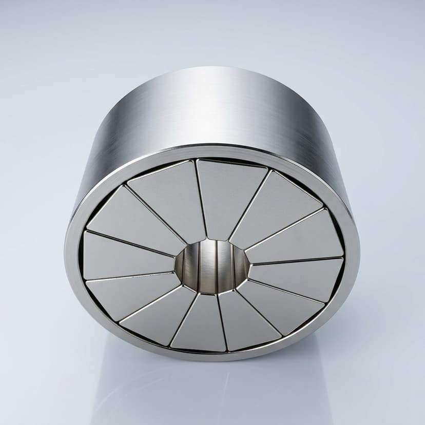
Halbach array magnetic levitation module
Linear Halbach motor track
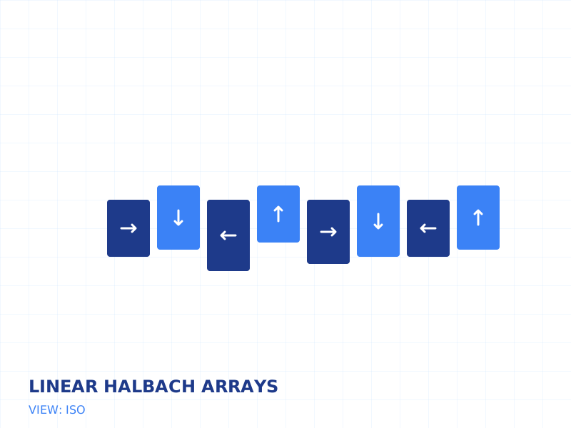
Linear Halbach array isometric engineering illustration
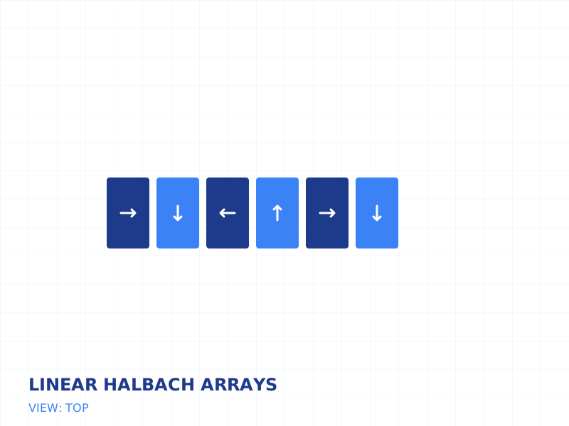
Linear Halbach array top-view magnetization layout

Buyer FAQ

Can you supply arrays longer than 1 meter?

Yes. Longer tracks are usually built from matched modular sections, with length and pitch tolerance set by the installation envelope and measurement plan.

Should we specify surface field or working-gap field?

Working-gap field is more useful for motor design because thrust is generated at the real air gap between coil and magnet track.

Can long linear tracks be shipped as matched sections?

Yes. For long tracks, modules can be measured, labeled, packed, and installed in sequence to reduce joint discontinuity.

Related Resources

Engineering RFQ Inbox

[email protected]

Include target torque/speed, quantity, and delivery location.

Direct Engineer Chat

WhatsApp Engineering Support

Use for drawing, specification, and RFQ clarification.