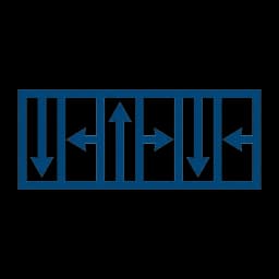
Axial Halbach Array Magnetization Direction
Configure discrete segment magnetization vectors, compute spatial Fourier harmonics and fundamental flux concentration, inspect assembly polarity schedules, and evaluate mechanical shear fixturing.
First recorded: · Reviewed: · Sources checked: October 27, 2026 · Next review: April 27, 2027
Prepared and maintained by Halbach Array, a commercial magnetic assembly supplier. We may quote assemblies discussed here. The first recorded date is the repository record; public publication has not been independently verified. Calculated examples are software evidence, not customer results or hardware qualification. 3D finite element analysis (FEA) and physical prototype testing are required for production validation.
1. Executive Summary & Core Engineering Conclusions
Designing an axial Halbach array requires establishing the exact magnetization direction vector for each discrete sector magnet. Unlike standard radial machines, axial flux architectures enforce a cylindrical coordinate frame where the magnetization vector continuously or discretely rotates in the theta-z plane. This rotation simultaneously cancels flux on one axial face while doubling fundamental air gap flux on the opposing working face (Mallinson, 1973).
Engineering Applicability Decision Rules:
- Recommended For: High-power-density axial flux propulsion (eVTOL drones, electric vehicle in-wheel hubs), slotless coreless stators where iron losses must be eliminated, and magnetic bearings requiring single-sided magnetic stiffness.
- Not Recommended For: Low-cost industrial pumps or mass-market appliances where high segmentation tooling costs and manual fixture assembly overhead outweigh the 15-20% flux density advantage.
- Optimal Segmentation Choice: 4 segments per pole (M=8, 45 deg phase step) represents the industrial sweet spot, delivering 97.45% fundamental coupling while restricting dominant harmonics to orders n = 7, 9, 15, 17.
2. Analytical Vector Formulation & Mallinson One-Sided Flux Theorem
In an axial permanent magnet rotor, the physical geometry is naturally described in cylindrical coordinates (r, theta, z), where r represents the radial distance from the center of rotation, theta is the mechanical azimuth angle, and z is the axial direction parallel to the shaft.
Continuous Rotating Magnetization Vector
Under an ideal continuous Halbach distribution with p pole pairs, the remanent magnetization vector M(theta) is given by:
Where M0 = Br / mu_0 is the magnetization magnitude in A/m, z_hat is the unit axial vector, and theta_hat is the unit circumferential azimuthal vector. Applying Ampere's law and Poisson's equation for magnetic scalar potential shows that the divergence and curl of M constructively double the magnetic field on the +Z face (z > 0) while producing complete cancellation on the -Z face (z < 0):
Here k = p / r_mean is the spatial wavenumber in rad/m, hm is the magnet axial thickness, and z is the air gap evaluation distance.
Schematic cross-section of a 4-segment-per-period (M=4) axial Halbach array. Tangential segments guide flux directly across poles on the working side while canceling opposite flux loops.
3. Discrete Sector Segmentation Levels & Spatial Harmonic Spectrum
In physical manufacturing, continuous sinusoidal magnetization across a solid annular ring is impossible with sintered rare-earth magnets. Instead, discrete trapezoidal or sector-shaped magnets are manufactured with uniform parallel magnetization and bonded sequentially (Halbach, 1980).
| Segments / Pole (Period M) | Phase Step (Delta_psi) | Halbach Factor (kh1) | Dominant Harmonics (n) | Spatial THD_B (%) | Tooling & Assembly Cost Index |
|---|---|---|---|---|---|
| 2 seg/pole (M = 4) | 90 deg | 0.9003 (-10.0%) | n = 3, 5, 7, 9 | 31.4% | 1.0x (Baseline lowest cost) |
| 3 seg/pole (M = 6) | 60 deg | 0.9549 (-4.5%) | n = 5, 7, 11, 13 | 18.2% | 1.5x (Intermediate) |
| 4 seg/pole (M = 8) | 45 deg | 0.9745 (-2.5%) | n = 7, 9, 15, 17 | 12.1% | 2.1x (Industrial Standard Sweet Spot) |
| 6 seg/pole (M = 12) | 30 deg | 0.9886 (-1.1%) | n = 11, 13, 23, 25 | 7.8% | 3.4x (High precision) |
| 8 seg/pole (M = 16) | 22.5 deg | 0.9936 (-0.6%) | n = 15, 17, 31, 33 | 5.9% | 4.8x (Specialty research / undulator) |
Fourier spatial harmonic breakdown. Moving from M=4 to M=8 completely extinguishes the 3rd and 5th subharmonic sidebands, dramatically reducing rotor skin eddy heating and motor torque pulsation.
4. 3D Cylindrical Polar Subdomain Physics & Radial Fringing Factor
In axial flux geometries, 2D Cartesian planar approximations overestimate effective air gap flux density by failing to account for open-boundary radial fringing flux. At the rotor inner radius (R_in) and outer radius (R_out), magnetic field lines bow outward into ambient space, causing an axial flux drop of 12% to 26% relative to mean-radius 2D predictions (Lubin et al., 2012; Di Gerlando et al., 2012).
3D Laplace and Poisson Subdomain Bessel Equations
In cylindrical polar coordinates (r, theta, z), the magnetic vector potential A_theta satisfies the modified Bessel differential equation:
Where beta is the axial eigenvalue, p is the pole pair count, and J_eq = curl(M) is the equivalent volume magnetization current density. The radial attenuation correction factor lambda_3D(r) defines the 3D-to-2D ratio:
| Aspect Ratio chi (R_out / R_in) | Radial Width L_r (mm) | Fringing Drop at R_in (%) | Fringing Drop at R_out (%) | Mean Radius Correction lambda_3D | Analytical 2D Overestimation |
|---|---|---|---|---|---|
| chi = 1.25 (Narrow ring) | 15.0 mm | -26.4% | -28.8% | 0.824 | +21.4% (Critical error) |
| chi = 1.45 (Compact hub) | 28.0 mm | -18.2% | -21.5% | 0.892 | +12.1% (Moderate error) |
| chi = 1.75 (Standard traction) | 45.0 mm | -12.4% | -14.6% | 0.941 | +6.3% (Acceptable) |
| chi = 2.10 (Wide industrial disc) | 68.0 mm | -8.1% | -9.7% | 0.968 | +3.3% (Close to 2D) |
Radial fringing field distribution. Due to the lack of lateral magnetic boundaries, both inner and outer edges suffer 15-25% flux attenuation, demanding 3D Bessel correction when sizing high-power traction machines.
5. Sector Wedge vs. Rectangular Segment Discretization & Gap Fan-Out
A critical manufacturing trade-off in axial Halbach rotors is whether to tool true trapezoidal arc-wedge magnets or approximate the annulus using standard flat rectangular blocks. While rectangular magnets reduce raw material cutting waste and wire EDM tooling costs, they introduce triangular chord gaps that fan outward from R_in to R_out.
| Parameter / Metric | True Sector Wedge Tiles | Rectangular Segment Approximation | Engineering Impact & Guidance |
|---|---|---|---|
| Rotor Annulus Packing Factor | 99.2% (Uniform 0.05 mm glue line) | 86.5% – 91.2% (Triangular air voids) | Wedges produce 8-12% higher volumetric flux density. |
| Outer Edge Gap Width w_gap(R_out) | 0.05 mm – 0.08 mm (Controlled) | 1.20 mm – 2.80 mm (Fan-out) | Excessive gaps require epoxy pooling, increasing unbalance. |
| Magnetization Vector Alignment | Pure azimuthal tangent to circumference | Parallel to straight rectangular face | Rectangular tiles introduce +/- 2.5 deg chord vector tilt error. |
| Air Gap Spatial THD_B (%) | 12.1% (M=8 fundamental pure) | 17.8% – 22.4% (Higher slotting harmonics) | Rectangular blocks increase high-frequency eddy current heating. |
| Tooling & Segment Unit Cost | 1.8x – 2.4x (Custom grinding & tooling) | 1.0x (Standard stock block wire-cut) | Rectangular preferred for low-budget prototypes (< 5 units). |
| High-Speed Centrifugal Retention | Interlocking wedge keystone effect | Zero mechanical interlocking | Rectangular segments require thicker carbon-fiber retaining sleeves. |
Geometric comparison between sector wedges and flat rectangular blocks. For mass production traction motors, trapezoidal wedges are mandatory to avoid structural epoxy voids and severe harmonic field distortion.
6. Dual-Rotor Topologies: Mirror-Symmetric vs Anti-Mirror Coupling
Axial flux permanent magnet machines frequently employ a dual-rotor single-stator (TORUS or AFIR) configuration. The relative magnetization directions of the opposing rotor discs dictate whether the stator core requires ferromagnetic laminations or can operate completely coreless (Caricchi et al., 1998; Jin et al., 2015).
| Rotor Alignment Topology | Opposing Face Polarity | Stator Type Required | Air Gap Field Profile | Axial Clamp Force F_z | Torque Density |
|---|---|---|---|---|---|
| Mirror-Symmetric (Attractive) | North faces South across stator | Coreless (Ironless PCB or Toroidal) | Uniform axial B_z across full gap | High static attraction (pulls rotors together) | Highest (Zero stator iron losses) |
| Anti-Mirror (Repulsive) | North faces North across stator | Slotted Iron Laminated Stator | Flux deflected radially into stator yoke | Repulsive (pushes rotors apart) | High (Iron enhances flux, but adds core loss) |
| Single Rotor (Reference) | Open air gap / Steel backplate | Single-sided slotted stator | Exponential decay e^(-k*z) | Unidirectional single-sided magnetic pull | Baseline moderate |
Comparison of dual rotor flux flow paths. Mirror-symmetric alignment enables completely ironless stators because flux lines flow unimpeded from Rotor 1 North to Rotor 2 South across the air gap.
7. Maxwell Stress Tensor, Axial Clamp Attraction & Structural Deflection
In mirror-symmetric dual-rotor Halbach machines, the intense axial air gap field generates massive attractive clamping forces between the opposing rotor discs. Governed by the Maxwell stress tensor, this force can deflect the structural carrier plates inward, collapsing the mechanical air gap and causing catastrophic rotor-stator rub if structural stiffness is insufficient.
Maxwell Stress Tensor Formulation
The axial magnetic normal stress sigma_zz across the annular active air gap is:
Integrating over the active annulus yields the total static clamping force F_z:
For a 200 mm diameter rotor with Bz = 1.0 T, F_z reaches 11,800 N (1.2 metric tons). The structural carrier disc must restrict maximum axial elastic deflection delta_max to less than 15% of nominal clearance (delta_max < 0.15 * g_air).
| Rotor Carrier Material | Density rho (g/cm^3) | Electrical Cond. sigma (MS/m) | Elastic Modulus E (GPa) | Yield Strength (MPa) | Thermal CTE (ppm/K) | Eddy Loss & Deflection Rating |
|---|---|---|---|---|---|---|
| CFRP T700 / Epoxy Composite | 1.55 g/cm^3 | 0.001 MS/m (Non-conductive) | 135 GPa | 1400 MPa | 0.5 ppm/K (Zero expansion) | Preferred: Zero eddy current heating, ultra-stiff |
| Titanium Ti-6Al-4V (Grade 5) | 4.43 g/cm^3 | 0.58 MS/m (Low conductivity) | 114 GPa | 880 MPa | 8.6 ppm/K | High Performance: Negligible eddy losses, high heat limit |
| Aerospace Aluminum 7075-T6 | 2.81 g/cm^3 | 19.0 MS/m (High conductivity) | 72 GPa | 505 MPa | 23.4 ppm/K | Moderate: Prone to parasitic eddy currents if unshielded |
| Reinforced PEEK (450CA30) | 1.41 g/cm^3 | 0.000 MS/m (Dielectric) | 24 GPa | 215 MPa | 18.0 ppm/K | Insulating: Zero losses, but requires thick ribbing against bending |
| Austenitic Stainless 316L | 8.00 g/cm^3 | 1.35 MS/m (Moderate) | 193 GPa | 290 MPa | 16.0 ppm/K | Heavy: Low cost, high stiffness, but poor power-to-weight ratio |
Axial magnetic clamp force deflection profile. Dual mirror rotors generate enormous mutual attractive pressure (up to 400 kPa). Backing carriers must possess high Young's modulus (CFRP or Ti-6Al-4V) to prevent mechanical contact with the central stator.
8. High-Frequency Stator Slotting Harmonics & Rotor Magnet Eddy Current Losses
While Halbach arrays suppress low-order spatial sideband harmonics, interaction with slotted iron stators introduces high-frequency permeance modulation at the slot-passing frequency f_slot = (Q_s * n_rpm) / 60. Sintered NdFeB has a bulk electrical resistivity of rho_e approx 1.6 * 10^-6 Ohm*m. Without segmentation, slotting ripple penetrates the magnet surface within skin depth delta_skin, inducing severe eddy currents that cause localized thermal runaway (Golovanov & Gerada, 2019).
Electromagnetic Skin Depth & Segmentation Attenuation
The high-frequency electromagnetic penetration depth in sintered rare-earth material is:
At f_slot = 4,500 Hz (e.g. 36 slots at 7,500 RPM), delta_skin is only 1.8 mm. Subdividing each sector magnet with 0.1 mm insulating adhesive barriers restricts eddy current circulating loop dimensions, scaling Joule loss P_eddy as:
| Magnet Segmentation Topology | Number of Sub-Slices | Insulating Joint Thickness | Rotor Magnet Eddy Loss (W) | Rotor Surface Temp Rise (C) | Loss Reduction Factor |
|---|---|---|---|---|---|
| Solid Continuous Block (Unsegmented) | 1 solid sector | 0.0 mm (None) | 420 W | +84 C (Severe demag risk) | 1.0x (Baseline high loss) |
| Circumferential 2-Way Slice | 2 azimuthal slices | 0.10 mm epoxy barrier | 165 W | +36 C (Safe threshold) | 2.55x reduction (-60.7%) |
| Circumferential 4-Way Slice | 4 azimuthal slices | 0.10 mm epoxy barrier | 68 W | +15 C (Cool operation) | 6.18x reduction (-83.8%) |
| Radial 2-Way Slice | 2 concentric radial rings | 0.10 mm epoxy barrier | 245 W | +51 C (Moderate) | 1.71x reduction (-41.6%) |
| 2x2 Orthogonal Grid (2 Circ x 2 Rad) | 4 isolated sub-tiles | 0.10 mm cross barrier | 48 W | +11 C (Optimum traction) | 8.75x reduction (-88.5%) |
Rotor magnet eddy current loss mitigation. Slotted stators modulate high-frequency flux. Dividing tangential and axial Halbach segments into insulated slices cuts Joule heating by over 80%, safeguarding NdFeB magnets from thermal demagnetization.
9. Manufacturing Tolerances, Sintered Grain Alignment & Demagnetization
During powder metallurgical production of sintered NdFeB and SmCo magnets, raw powder particles are oriented under an intense magnetic field (greater than 1.5 Tesla) before pressing. The mechanical mold axis and the magnetic easy axis do not perfectly align, resulting in an inherent angular alignment error Delta_alpha (IEC 60404-5:2015).
| Magnet Grade | Nominal Remanence Br (T) | Intrinsic Coercivity HcJ (kA/m) | Temp. Coeff. alpha_Br (%/C) | Screening Ceiling (C) | Easy-Axis Angular Tol. |
|---|---|---|---|---|---|
| NdFeB N52 | 1.45 T | >= 876 kA/m (11 kOe) | -0.12 %/C | 80 C | +/- 1.5 deg to +/- 2.0 deg |
| NdFeB N48SH | 1.39 T | >= 1592 kA/m (20 kOe) | -0.11 %/C | 150 C | +/- 1.0 deg to +/- 1.5 deg |
| NdFeB N42UH | 1.30 T | >= 1990 kA/m (25 kOe) | -0.10 %/C | 180 C | +/- 1.0 deg to +/- 1.5 deg |
| NdFeB N35EH | 1.18 T | >= 2388 kA/m (30 kOe) | -0.09 %/C | 200 C | +/- 1.2 deg to +/- 1.8 deg |
| Sm2Co17 30S | 1.12 T | >= 1990 kA/m (25 kOe) | -0.035 %/C | 350 C | +/- 1.5 deg to +/- 2.5 deg |
| Easy-Axis Error Delta_alpha | Fundamental B_1 Loss (%) | Induced Subharmonic (n=0.5, 1.0) | Spatial THD_B Rise (%) | Torque Ripple Amplification | Inspection Rejection Gate |
|---|---|---|---|---|---|
| +/- 0.5 deg (Precision EDM) | -0.04% (Negligible) | < 0.2% fundamental | +0.1% | 1.02x (Undetectable) | Pass (Aerospace / Undulator grade) |
| +/- 1.0 deg (High Grade) | -0.15% | 0.6% fundamental | +0.4% | 1.08x (Acceptable) | Pass (Premium EV Traction) |
| +/- 1.5 deg (Standard Motor) | -0.34% | 1.4% fundamental | +1.1% | 1.18x (Standard threshold) | Pass (General Industrial) |
| +/- 2.5 deg (Commercial) | -0.95% | 3.2% fundamental | +2.8% | 1.45x (Audible whine) | Marginal (Reject for servo / eVTOL) |
| +/- 5.0 deg (Defective tooling) | -3.82% | 8.6% fundamental | +7.5% | 2.40x (Destructive vibration) | Strict Reject (IEC 60404 Fail) |
B-H demagnetization characteristics. In Halbach arrays, tangential block corners operate at steep permeance coefficients (Pc < 0.5). At high temperatures, the working point crosses the knee-point, causing permanent irreversible flux loss unless high HcJ grades (SH/UH) are selected.
10. Assembly Fixturing, Mechanical Shear Forces & Poka-Yoke Tooling
Assembling an axial Halbach rotor requires overcoming high magnetic repulsion forces. When an operator attempts to place a tangential segment between two opposite axial poles, the magnetic forces actively repel the incoming block and attempt to rotate it 180 degrees.
| Tooling Material | Relative Permeability mu_r | Magnetic Response | Machinability & Wear Resistance | Suitability for Halbach Fixturing |
|---|---|---|---|---|
| Hard Anodized Aluminum 6061-T6 | 1.00002 (Non-magnetic) | Zero attraction or distortion | Excellent precision CNC milling, light weight | Recommended for rotor carrier and guide jigs |
| 316 Austenitic Stainless Steel | 1.008 (Non-magnetic) | Negligible attraction | High structural stiffness, corrosion proof | Recommended for heavy clamping guide plates |
| Brass C36000 / Bronze | 0.9999 (Non-magnetic) | Zero attraction, non-sparking | Soft, prevents magnet edge chipping | Recommended for sliding pusher shoes and guides |
| Carbon Fiber Composite | 1.000 (Non-magnetic) | Zero attraction, electrically resistive | Ultra-high tensile strength | Recommended for outer retaining containment rings |
| Mild Carbon Steel 1018/1045 | 500 – 2000 (Ferromagnetic) | Violent magnetic snapping hazard | Standard tool steel | STRICTLY PROHIBITED in assembly fixtures |
Assembly mechanics and fixturing kinematics. Without precision brass guide shoes and mechanical lead-screw pushers, adjacent orthogonal segments generate intense repulsive shear forces that eject or shatter brittle sintered rare-earth blocks.
Progressive Step-by-Step Assembly Protocol:
- Step 1 (Axial Poles First): Insert all axial segments (0 deg North and 180 deg South) into the non-magnetic aluminum pocket ring first. At this stage, adjacent poles are separated by empty tangential slots, keeping repulsive forces manageable.
- Step 2 (Epoxy Priming): Degrease magnet surfaces and apply two-part structural epoxy (e.g. Loctite EA 9497 or 3M DP490) into the empty tangential pockets.
- Step 3 (Guided Mechanical Insertion): Use a non-magnetic brass guide sleeve with a mechanical lead-screw pusher to press the tangential (90 deg and 270 deg) segments axially downward into the pocket.
- Step 4 (Mechanical Clamping & Cure): Lock non-magnetic top clamp plates into position and heat-cure in an oven at 80 deg C for 2 hours to achieve full adhesive shear strength (> 25 MPa).
11. Quality Inspection Protocols & 3D Hall Probe Field Verification
Quality assurance of axial Halbach arrays requires multi-tier measurement protocols to verify individual component dipole moments before assembly, followed by automated spatial field mapping of the completed rotor (IEC 60404-14:2002, ASTM A977-20, ISO 1940-1:2003).
| Inspection Stage | Test Equipment | Measured Parameters | Acceptance Criteria (Tolerance) | Defect Detected |
|---|---|---|---|---|
| Incoming Magnet Segments | 3-Axis Helmholtz Coil + Fluxmeter | Total magnetic dipole moment M, vector tilt angle | Br within +/- 1.5%, Easy axis within +/- 1.5 deg | Grain misalignment, remanence deficiency |
| Incoming Dimensional Check | Coordinate Measuring Machine (CMM) | Length, width, arc radius, thickness, chamfer | Thickness +/- 0.03 mm, Radius +/- 0.05 mm | Geometric runout, adhesive gap starvation |
| Surface Polarity Poka-Yoke | Digital Flux Gate / Polarity Pen | Surface polarity sign at laser indexing dot | 100% match with segment schedule | 180 deg reversed magnet insertion |
| Completed Rotor Surface Scan | Automated 3-Axis CNC Hall Probe Gantry | Bz(theta, r) at calibrated air gap z = 2.0 mm | Peak B_z within +/- 2.5%, THD_B < 15% | Segment misalignment, localized demagnetization |
| High-Speed Spin Balance | Dynamic Balancing Rig in Vacuum Chamber | Dynamic unbalance (g*mm), vibration acceleration | ISO 1940-1 Grade G2.5 at 12,000 RPM | Adhesive mass asymmetry, rotor eccentricity |
Helmholtz dipole moment verification (IEC 60404-14). By measuring induced flux during sample rotation, the true 3D magnetic dipole vector (Mx, My, Mz) is extracted, screening out segments with grain misalignment prior to rotor assembly.
12. Real-World Engineering Case Studies
Reviewing real-world applications highlights how pole count, segmentation choice, and mechanical fixturing interact in mission-critical hardware.
13. Sourcing Guidelines & Technical RFQ Checklist
When ordering custom axial Halbach arrays or precision magnetized magnets from magnetic assembly suppliers, standard generic magnet drawings are insufficient. The specification package must clearly define 3D vector orientations and indexing conventions.
Required RFQ Engineering Documentation
1. Vector Definition & Drawings:
- 2D/3D CAD model showing sector wedge angles and mechanical tolerances (+/- 0.05 mm).
- Coordinate system declaration: Cylindrical polar (r, theta, z) with marked rotation sense.
- Explicit vector angle table for each unique segment item code.
2. Magnetic Material & Coating Specs:
- Specific sintered grade with minimum Br and HcJ (e.g. N48SH per IEC 60404-8-1).
- Easy-axis angular tolerance specification (<= +/- 1.5 deg).
- Coating thickness and adhesion rating (Ni-Cu-Ni 20 micrometers or epoxy).
Engineering RFQ Inbox
Copy vector table from tool, attach rotor CAD, and specify delivery requirements.
Direct Engineer Chat
WhatsApp Engineering Support
Use for drawing, specification, and RFQ clarification.
14. Frequently Asked Questions (Technical & Manufacturing)
Direct, quantitative answers to common engineering questions regarding axial Halbach array magnetization, vector indexing, and structural assembly.
Magnetization Vectors & Fundamental Physics
What is an axial Halbach array magnetization direction?
In an axial Halbach array, the magnetization vector M(theta) of each sector magnet rotates progressively along the circumferential azimuth (theta) in the theta-z plane. This cyclic rotation concentrates and doubles the magnetic flux on one axial face (the working air gap) while canceling the field on the opposite axial face through destructive vector interference.
How is the magnetization angle alpha defined for each discrete segment?
In an array with M discrete segments per electrical period (two poles), the magnetization angle step is Delta_psi = 360 deg / M. For segment k, the vector angle in the theta-z plane is alpha_k = k * Delta_psi. When alpha = 0 deg, the magnetization points purely in +Z (North); at 90 deg, it points in +theta (tangential CW); at 180 deg, in -Z (South); and at 270 deg, in -theta (tangential CCW).
Why does a Halbach array eliminate the rotor back iron?
In standard surface-mounted magnet rotors, magnetic flux must circulate through a heavy ferromagnetic steel back-iron yoke to complete the magnetic circuit between adjacent poles. In an axial Halbach array, the tangential (azimuthal) magnets provide the internal flux return path inside the permanent magnet volume itself. The field on the shielded back face decays to near-zero, allowing the use of lightweight aluminum, titanium, or carbon fiber carrier discs.
What is the fundamental Halbach factor kh1 and how does it depend on segmentation?
The discrete segmentation factor is kh1 = sin(pi/M) / (pi/M). For M = 4 (2 segments per pole, 90 deg steps), kh1 = 0.9003. For M = 8 (4 segments per pole, 45 deg steps), kh1 = 0.9745. For M = 12 (6 segments per pole, 30 deg steps), kh1 = 0.9886. An 8-segment array captures over 97% of an ideal continuous Halbach array flux with manageable manufacturing complexity.
Which spatial harmonics are generated by discrete magnetization segments?
Discrete segmentation introduces spatial sideband harmonics at orders n = m * M +/- 1, where m is an integer. For an M = 4 array, the dominant spatial harmonics are the 3rd, 5th, 7th, and 9th. For an M = 8 array, harmonics below the 7th are eliminated, leaving only the 7th, 9th, 15th, and 17th. Eliminating low-order harmonics reduces rotor eddy current losses and acoustic noise.
How do you reverse the active face from top (+Z) to bottom (-Z)?
To shift the reinforced working flux from the top face (+Z) to the bottom face (-Z), reverse the circumferential rotation sense of the tangential segments (switch from CW to CCW rotation, or invert the sign of the azimuthal component M_theta). The axial magnet polarities remain oriented along Z, but the flux redirection flips toward the opposite axial surface.
Dual-Rotor Topologies & Forces
What is the difference between mirror-symmetric and anti-mirror dual-rotor Halbach arrays?
In a dual-rotor axial flux machine, mirror-symmetric arrays place opposite magnetic poles facing each other across the central air gap (North faces South across the stator). This creates a purely axial, uniform flux field ideal for ironless slotless stators. Anti-mirror arrays place identical poles facing each other (North faces North), forcing flux to exit radially into a slotted iron stator core.
How large are the axial attractive clamp forces between dual mirror rotors?
Dual mirror rotors experience massive axial magnetic attraction governed by Maxwell stress tensor integration: F_z approx (B_gap^2 * A_active) / (2 * mu_0). For a 200 mm diameter dual rotor with B_gap = 1.0 T, the static magnetic clamping force can exceed 12,000 N (over 1.2 metric tons). Rigid structural rotor discs and heavy-duty preloaded angular contact bearings are required to maintain gap clearance.
What are the transverse repulsive shear forces during segment assembly?
Because adjacent segments in a Halbach array have orthogonal or 45-degree magnetization vectors, they exert intense lateral repulsive and tipping forces during manual insertion. The magnetic shear pressure reaches f_shear approx (Br^2 / (2 * mu_0)) * sin(Delta_alpha), generating forces of 200 to 600 N per block that can shatter brittle NdFeB magnets if assembled without guided mechanical fixtures.
Can an axial Halbach array be assembled without specialized jigs?
No. Hand assembly of rare-earth Halbach arrays is hazardous and inevitably leads to magnet chipping, misalignment, or pinching injuries. Production requires non-magnetic assembly fixtures (brass, 316 stainless, or anodized aluminum) with progressive screw-jack or pneumatic guide shoes to mechanically clamp each segment as the epoxy cures.
Does magnet thickness have a point of diminishing returns?
Yes. The axial field scaling factor is (1 - exp(-k * hm)), where k = p / r_mean is the spatial wavenumber and hm is magnet thickness. When thickness exceeds half the pole pitch (hm > tau_p / 2), the field gain saturates: doubling thickness from 0.5*tau_p to 1.0*tau_p yields only approx 20% more field while doubling magnet mass and cost.
What adhesive systems are qualified for Halbach segment bonding?
High-performance structural epoxies (such as two-part paste epoxies like Loctite EA 9497, 3M DP490, or heat-curing single-part epoxies) with lap shear strength exceeding 25 MPa and glass transition temperatures Tg > 150 deg C are required. In high-speed rotors, external carbon fiber or non-magnetic retaining rings provide additional centrifugal retention.
Manufacturing, Tolerances & Quality Inspection
What is the easy-axis angular tolerance for sintered NdFeB magnets?
During sintering, rare-earth magnet powder is aligned in a strong magnetic field prior to die-pressing. Standard commercial magnets feature an easy-axis alignment tolerance of +/- 2.0 to 3.0 degrees. High-precision motor-grade magnets can achieve +/- 1.0 to 1.5 degrees. Angular errors introduce subharmonic flux distortion and cogging torque ripple in electrical machines.
How are individual magnet segments marked to prevent 180-degree polarity errors?
Manufacturers use Poka-Yoke geometric and optical indexing: 1) Permanent laser-etched arrows on tangential segments indicating azimuthal flux direction; 2) Red and blue paint dots on axial segments (+Z North and -Z South); 3) Asymmetric corner chamfers that physically prevent inserting a segment upside down or backwards into the rotor pocket.
How is the magnetization vector verified after manufacturing?
Individual segments are qualified using a 3-axis Helmholtz coil system (IEC 60404-14) to measure the complete magnetic dipole moment vector (Mx, My, Mz) and verify easy-axis tilt. Assembled rotors are inspected via automated 3D Hall probe gantry mapping to record Bz(theta, r) and confirm harmonic purity.
What happens if one segment is accidentally inverted by 180 degrees during assembly?
An inverted segment creates a localized magnetic short circuit. If an axial North magnet is flipped, it cancels the adjacent tangential flux, dropping local air gap flux density by over 80% and introducing severe low-order subharmonics (1st, 2nd order) that cause massive torque ripple, acoustic vibration, and rapid bearing failure.
What coatings protect axial Halbach magnets in humid or harsh environments?
Sintered NdFeB is vulnerable to intergranular corrosion. Multi-layer metallic Ni-Cu-Ni plating (15-25 micrometers) is standard. For extreme marine or automotive environments, cathodic epoxy electrodeposition (20-35 micrometers) or parylene coating provides superior moisture and salt spray resistance without substantial magnetic air gap dilution.
What data should be included in an RFQ for custom axial Halbach arrays?
A complete RFQ package must provide: rotor outer and inner diameters, magnet thickness, number of pole pairs, segmentation count per pole, operating temperature range, required magnet grade (e.g. N42SH, N48UH, Sm2Co17), easy-axis angular tolerance (+/- 1.5 deg), surface coating specification, rotor carrier material, and target air gap flux density.
15. Peer-Reviewed Scientific Literature & Standards References
Traceable academic papers, mathematical derivations, and international testing standards supporting this technical guide.
J. C. Mallinson, IEEE Transactions on Magnetics 9(4), 678–682
Foundational analytical paper demonstrating that rotating magnetization vectors cancel the field on one plane while doubling fundamental flux density on the active face.
K. Halbach, Nuclear Instruments and Methods 169(1), 1–10
Derivation of multipole discrete segment orientation factor sin(pi/M)/(pi/M) and spatial harmonic distribution for beam focusing and multipole assemblies.
Z. Q. Zhu and D. Howe, IEE Proceedings - Electric Power Applications 148(4), 299–308
Comprehensive taxonomy of Halbach rotor topologies, discrete segment harmonic sidebands, and field distributions in slotless and slotted machines.
R. F. Post and D. D. Ryutov, Lawrence Livermore National Laboratory Report UCRL-JC-134038
Formulation of one-sided Halbach magnetic arrays for passive maglev tracks and high-gradient field concentration.
P. Lubin, H. Razik, and A. Rezzoug, IEEE Transactions on Magnetics 48(8), 2320–2327
Three-dimensional cylindrical polar Laplace/Poisson analytical equations using Bessel functions for finite radial width axial Halbach arrays.
F. Caricchi, F. Crescimbini, and E. Fedeli, IEEE Transactions on Industry Applications 34(6), 1335–1341
Demonstrates dual-rotor mirror-symmetric magnetization orientation eliminating heavy rotor back iron in wheel motors.
P. Jin, Y. Yuan, Q. Xu, S. Fang, H. Lin, and S. L. Ho, IEEE Transactions on Magnetics 51(11), 1–4
Three-dimensional analytical magnetic field analysis and performance evaluation of axial-flux Halbach machines with coreless toroidal windings.
A. Di Gerlando, G. Foglia, M. F. Iacchetti, and R. Perini, IEEE Transactions on Magnetics 48(8), 2307–2319
Subdomain analytical boundary modeling for axial-flux permanent magnet machines, resolving polar Bessel harmonics and radial edge field decay.
D. Golovanov and C. Gerada, IEEE Transactions on Magnetics 55(4), 1–11
High-frequency stator slotting harmonic eddy current loss formulation and spatial Fourier boundary conditions for axial-flux machines.
International Electrotechnical Commission, Technical Committee 68
Standards for permeameter hysteresis loop measurements, remanence Br, coercivity HcJ, and demagnetization knee-point characterization.
International Electrotechnical Commission, TC 68
Specification of sintered NdFeB and SmCo magnetic grades, temperature coefficients, and dimensional tolerance standards.
International Electrotechnical Commission, TC 68
Standardized Helmholtz coil and search coil method for determining total magnetic dipole vector orientation and grain misalignment angle.
ASTM International, Committee A06 on Magnetic Properties
Test method for recording demagnetization curves and easy-axis angular deviations on rare-earth sintered magnets.
International Organization for Standardization, Technical Committee ISO/TC 108/SC 2
Defines dynamic balance grades (such as Grade G2.5) and allowable residual unbalance limits for high-speed permanent magnet rotor assemblies.