
Halbach Array Segment Count: 4 vs 8 vs 16 Blocks (Cost & Performance)
Compare Halbach array segment counts across 4, 8, and 16 blocks: flux, ripple, eddy-current risk, cost drivers, QC checks, and RFQ guidance.
While a 16-segment Halbach array achieves nearly 95% of an ideal continuous magnetic flux, the exponential increase in assembly cost means an 8-segment design is often the most commercially viable choice for standard industrial applications. This guide provides engineering and procurement teams with a data-driven framework to select the optimal segment count (4, 8, or 16) by balancing magnetic field homogeneity, torque ripple, eddy current losses, and manufacturing complexity.
The decision of how many segments to use in a Halbach array is one of the most consequential choices in magnetic design. It dictates not only the electromagnetic performance of the final device but also the supply chain viability, yield rates, and unit economics. In this comprehensive technical guide, we will explore the physics, economics, and practical boundaries of segmenting a Halbach array.
Last reviewed: July 19, 2026. Scope: Global OEM procurement and engineering reviews for discrete-block Halbach rotors, Halbach cylinders, magnetic couplings, magnetic gears, and custom linear modules. The percentages and cost multipliers below are normalized decision ranges, not universal guarantees; final selection still depends on bore/OD ratio, magnet grade, adhesive system, sleeve design, speed, temperature, and FEA validation.
1. Executive Summary: The Segment Count Trade-off
For buyers and engineers evaluating OEM magnetic assemblies, the choice of segment count is rarely a simple "more is better" equation. Increasing the number of discrete magnets per magnetic pole pair dramatically alters the project's risk profile.
For a live RFQ, provide bore/OD, stack length, target air-gap flux density, maximum RPM, duty cycle, magnet grade, surface-temperature limit, and required inspection evidence through Contact / RFQ. Those inputs determine whether an 8-segment design is enough or whether a 16-segment design is justified.
The Law of Diminishing Returns
Going from 4 to 8 segments yields a massive jump in field strength and uniformity. However, going from 8 to 16 segments offers a much smaller incremental gain in flux density, while disproportionately increasing manufacturing costs and assembly failure risks.
The 8-Segment Industry Standard
For over 80% of commercial BLDC (Brushless DC) motors and magnetic couplings, the 8-segment configuration represents the optimal "sweet spot." It minimizes torque ripple to acceptable levels without requiring aerospace-grade assembly tolerances.
Eddy Current Mitigation
In high-speed rotor applications (>20,000 RPM), higher segment counts (16+) are often mandated. This is not primarily for flux shaping, but to physically break up the conductive volume of the magnet, thereby reducing eddy current losses and thermal demagnetization risks.
Tolerance Compounding
Every added segment introduces another layer of angular deviation and dimensional tolerance stack-up. A 16-segment array demands specialized non-magnetic fixturing and strict QC on raw block magnetization angles (<1.5° deviation).
2. The Physics of Segmentation: Why We Slice the Magnet
To understand why we debate over 4, 8, or 16 segments, we must first look at the theoretical ideal: the continuously varying Halbach cylinder (also known as a K. Halbach dipole or multipole). In a mathematically perfect Halbach array, the direction of magnetization rotates smoothly and continuously around the cylinder or along the linear track. This produces a perfectly sinusoidal magnetic field on the working side (e.g., the bore of the cylinder) and exactly zero magnetic field on the shielded side.
However, manufacturing an anisotropic permanent magnet (like NdFeB or SmCo) with a continuously rotating magnetic vector is practically impossible at commercial scale. The magnetization direction is locked into the crystalline structure during the powder pressing and sintering phases in the presence of a strong aligning magnetic field.
Therefore, engineers must approximate this continuous rotation by assembling discrete, pre-magnetized blocks. The number of blocks used to complete one full 360-degree rotation of the magnetization vector (one pole pair) is the segment count.
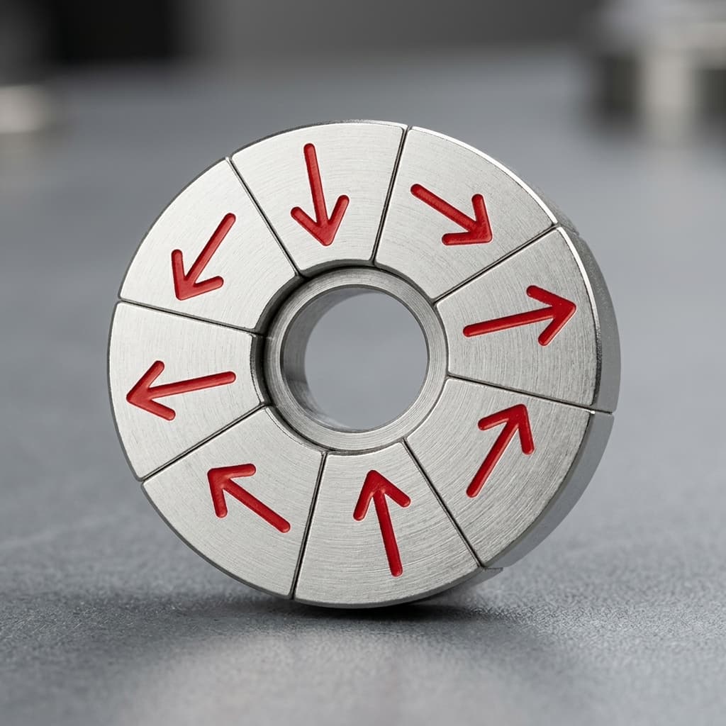
Visualizing Segment Count: 4 vs 8 Segments
As we increase the segment count (e.g., from 4 to 8 to 16), the angle of magnetization changes in smaller increments (90°, 45°, 22.5° respectively). Smaller angle increments result in a smoother, more sinusoidal magnetic field profile.
3. Data-Driven Comparison: 4 vs 8 vs 16 Segments
To facilitate objective procurement and engineering decisions, we must quantify the impact of segment count. The following structured table outlines the relative performance, cost, and typical applications for each configuration.
Method note: Flux-density ranges are normalized against an ideal continuous Halbach field and cross-checked against published segmented/quasi-Halbach modeling trends plus supplier DFM experience. Cost multipliers include raw magnet count, machining kerf loss, sorting, non-magnetic fixture time, adhesive cure control, scrap risk, and final quality inspection. Use this table as a first-pass selection tool before electromagnetic simulation and prototype testing.
| Segment Count per Pole Pair | Magnetization Angle Increment | Approx. Flux Density (vs Ideal) | Spatial Harmonic Distortion | Assembly Difficulty | Relative Cost Multiplier | Ideal Engineering Applications |
|---|---|---|---|---|---|---|
| 2 Segments | 180° | ~60 - 65% | Extreme | Very Low | 0.8x | Primitive magnetic assemblies, academic demonstrations (rarely used industrially). |
| 4 Segments | 90° | ~70 - 75% | High | Low (Standard fixturing) | 1.0x (Baseline) | Simple magnetic latches, basic holding fixtures, low-speed educational models, some planar conveyors. |
| 8 Segments | 45° | ~85 - 90% | Moderate | High (Custom aluminum jigs) | 2.2x | Most commercial BLDC motors, wind turbine generators, magnetic couplings, industrial sensor targets. |
| 12 Segments | 30° | ~90 - 93% | Low | Very High | 3.5x | Specialized servo motors, medium-speed UAV propulsion, optimized magnetic gearboxes. |
| 16 Segments | 22.5° | ~93 - 96% | Very Low | Extreme (Precision constrained jigs) | 4.5x | MRI machines, high-speed UAV motors, particle accelerators, ultra-precision positioning stages. |
| 32 Segments | 11.25° | ~97 - 99% | Negligible | Unviable for most | >10.0x | Niche aerospace research, theoretical physics equipment. |
Note: The "Relative Cost Multiplier" includes both the bill of materials (raw blocks) and the labor/fixturing costs associated with the assembly process. Pricing scales non-linearly due to exponential increases in assembly rejection rates at higher segment counts.
4. Deep Dive: The 4-Segment Array (The Proof of Concept)
The 4-segment Halbach array is the simplest possible configuration. The magnetization vector rotates by 90 degrees with each adjacent block.
Engineering Advantages:
- Lowest Cost: Requires the fewest raw magnet blocks and minimal machining.
- Easy Assembly: The repulsive forces between blocks are manageable, and standard mechanical clamps can often be used to hold the magnets while the structural adhesive cures.
Applicability Boundaries:
- Not Suitable For: High-precision motors. The 90-degree abrupt changes in magnetization create massive spatial harmonics. If used in a motor rotor, this results in severe "cogging torque" (torque ripple), causing vibration, acoustic noise, and uneven power delivery.
- Suitable For: Static applications where the only goal is to concentrate flux on one side and shield the other, such as magnetic whiteboards, simple linear tracks, or low-cost holding devices.
5. Deep Dive: The 8-Segment Array (The Industry Workhorse)
By doubling the segment count to 8, the magnetization angle changes in 45-degree increments. This configuration is widely considered the industry standard for commercial motion control applications.
Engineering Advantages:
- The Sweet Spot for Uniformity: The 8-segment array eliminates the most severe harmonic distortions found in the 4-segment design. It produces a nearly sinusoidal field that pairs perfectly with standard 3-phase motor stators.
- Reasonable Cost: While more expensive than a 4-segment array, the 8-segment design is heavily optimized by Chinese supply chains. Experienced factories have standardized tooling and adhesive curing profiles for 45-degree block assemblies.
Manufacturing Risks & Trade-offs:
- Angular Deviation Sensitivity: At 8 segments, the raw magnet block's "true magnetic axis" must be tightly controlled. If a 45-degree block is accidentally magnetized at 48 degrees, the error will propagate through the entire ring, distorting the waveform. Procurement teams must demand sorting data from the supplier proving that raw blocks have
<1.5°of angular deviation.
6. Deep Dive: The 16-Segment Array (Precision & Aerospace)
A 16-segment array (22.5-degree increments) is a high-end engineering solution used when absolute field homogeneity or extreme eddy current reduction is required. It achieves up to 96% of the flux density of a theoretically perfect Halbach cylinder.
The Hidden Cost Drivers:
- Tolerance Compounding (Tolerance Stack-up): If you glue 16 blocks into a circle, any microscopic variance in the width of the blocks or the thickness of the glue line compounds 16 times. If the tolerance stack is not perfectly calculated, the final block will either not fit, or it will leave a large wedge-shaped air gap.
- Extreme Repulsive Forces: As you force magnets with only a 22.5-degree difference in magnetization together, the repelling forces are immense. If a block slips during assembly, it can shatter violently.
- Fragility: To fit 16 segments into a small motor rotor (e.g., 50mm diameter), each individual magnet block must be extremely thin. Thin NdFeB blocks are brittle and prone to chipping during handling and gluing.
The Thermal Advantage (Eddy Currents): Why would an engineer specify 16 segments if 8 is usually "good enough" for flux density? Thermal management. In high-speed motors (e.g., drone propulsion, turbomachinery), the rapidly changing magnetic fields in the stator induce eddy currents inside the rotor magnets. NdFeB magnets are highly conductive. By slicing the magnet into 16 separate pieces, you physically break the electrical circuit, restricting the flow of eddy currents. This dramatically lowers the operating temperature of the rotor, preventing catastrophic thermal demagnetization (which occurs above 150°C for standard grades).
7. Procurement & Engineering Decision Checklist
Before issuing a Request for Quotation (RFQ) or placing a Purchase Order for a Halbach array, use this framework to validate your segment count:
- Determine the Goal: Are you optimizing for static holding force, or dynamic motor rotation? (If static, default to 4 or 8 segments. If dynamic, default to 8 or 16).
- Analyze Torque Ripple Limits: Does your application have strict NVH (Noise, Vibration, and Harshness) requirements? If yes, a minimum of 8 segments is mandatory.
- Calculate Eddy Current Losses: Will the array rotate at speeds exceeding 15,000 RPM? If yes, run an FEA (Finite Element Analysis) simulation to see if 16 segments are required purely for thermal management.
- Audit Supplier Fixturing: For 8 and 16 segment arrays, ask the supplier: "Can you provide CAD renderings or photos of the custom non-magnetic assembly jigs you will use?" If they use manual clamping, reject the supplier.
- Set Angular Tolerances: Specify in the PO that the raw block magnetization angular deviation must be
<= 1.5°, and request raw sorting data before final assembly.
If the checklist points to 16 segments but your program cannot tolerate the tooling or yield risk, compare a simplified custom Halbach assembly with a retained 8-segment design, larger air gap, higher-grade material, or a revised stator waveform before locking the PO.
8. Risk Management and Quality Control
When pushing the boundary to higher segment counts, the primary risk shifts from electromagnetic design to mechanical assembly.
Critical Risk: Adhesive Failure and Rotor Disassembly
In 16-segment high-speed rotors, the internal repulsive forces combine with immense centrifugal forces during operation. If the structural epoxy (e.g., Loctite EA) is improperly cured, or if the outer carbon-fiber containment sleeve is poorly tensioned, the array will explode radially, destroying the stator.
Mitigation Strategy: Always require the supplier to perform a spin-test (overspeed test) on the first-article prototypes, running the assembled array at 120% of its rated maximum RPM in a safe containment chamber. Additionally, demand a 3D Gauss mapping report of the final assembly to verify that the theoretical waveform matches the manufactured reality.
9. Frequently Asked Questions (FAQ)
Q: Can we use odd segment counts, like 5 or 7 segments per pole? A: While mathematically possible, odd segment counts are almost never used in industrial Halbach arrays. They create asymmetric flux paths, unbalanced mechanical forces, and complicate both the motor winding design and the manufacturing jigs. Always use even counts, typically powers of 2 (4, 8, 16, 32).
Q: Does doubling the segment count from 8 to 16 double the magnetic field strength? A: No. A 4-segment array gives you roughly 75% of the ideal field. An 8-segment gives you ~88%. A 16-segment gives you ~95%. The performance curve flattens rapidly. You are paying for uniformity and thermal management, not raw strength.
Q: Why do suppliers charge a massive premium for 16-segment arrays? A: The cost of the raw NdFeB material is only slightly higher (due to kerf loss from cutting more pieces). The cost multiplier comes entirely from labor, custom precision tooling, longer adhesive curing cycles, and lower yield rates during final quality inspection.
Q: How does segment count affect the cost of the containment sleeve? A: Higher segment counts (like 16) approximate a perfect circle much better than 4 segments (which form a jagged octagon). Therefore, a 16-segment array requires less post-assembly grinding to achieve a perfectly round outer diameter, making it easier to press-fit or shrink-wrap a titanium or carbon fiber retention sleeve.
10. Sources and References for Further Reading
Use these sources to validate the physics and modeling direction behind the selection framework. The commercial cost multipliers remain application-specific RFQ estimates, not values copied from any single paper.
- Klaus Halbach, Lawrence Berkeley Laboratory: Design of Permanent Multipole Magnets with Oriented Rare Earth Cobalt Material; foundational continuous Halbach multipole reference. Link
- Eindhoven University of Technology: Quasi-Halbach segment-count modeling showing how higher segment counts can increase air-gap flux density while introducing glue-layer and eddy-current trade-offs. Link
- Energies / MDPI: Permanent-magnet segmentation study covering eddy-current loss reduction behavior and design trade-offs. Link
- Dura Magnetics Technical Overview: Practical explanation of circumferential and planar Halbach arrays for industry readers. Link
Partner with HalbachArray
Choosing the correct segment count is only the first step. Executing that design with tight angular tolerances and bulletproof structural adhesives is what separates a working prototype from a failed production run.
At HalbachArray, we specialize in bridging the gap between your FEA simulations and China's premier magnetic manufacturing supply chain. We audit factories, validate custom assembly jigs, and guarantee that your 8-segment or 16-segment arrays meet exact 3D Gauss mapping specifications.
If your engineering or procurement team is currently navigating a complex magnetic assembly project, reach out to us with your CAD files and performance targets.
Contact us today at [email protected] or through Contact / RFQ for a DFM (Design for Manufacturing) review and a comprehensive quotation.
Author

Categories
More Posts
Halbach Array vs. Traditional Magnets: When to Choose Which
An engineering comparison between Halbach arrays and traditional multipole magnet rotors for BLDC motors, eVTOLs, and industrial applications.

Halbach Array Quality Control: Essential Factory Testing and Validation Metrics for Buyers
Halbach Array QC guide for OEM buyers: validate 3D flux maps, Helmholtz coil data, angular deviation, CMM, salt spray, and RFQ pass/fail metrics for sourcing.
Halbach Array Assembly Tolerances: Mechanical Precision vs. Magnetic Performance
Learn how Halbach array assembly tolerances affect flux, yield, and cost, with an RFQ decision matrix and supplier checks for precision magnetic builds.