
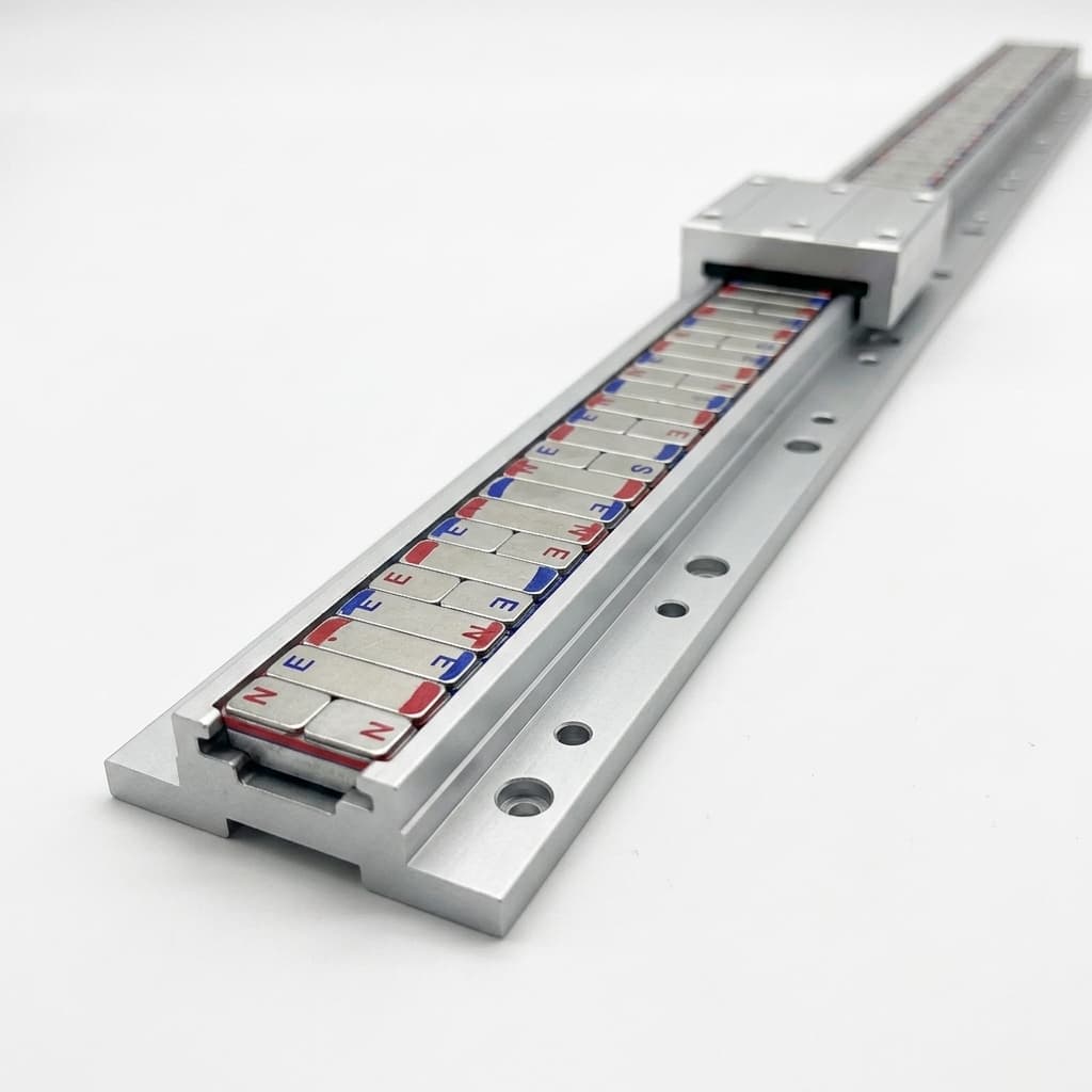
Halbach Array Linear Motor Tracks: Modular Pitch Splicing, Thrust Ripple Control, and Sourcing Guide
Source Halbach array linear motor tracks: compare splice designs, assess thrust ripple and thermal limits, and use the RFQ checklist to request a design review.
A Halbach array linear motor track uses a rotating sequence of permanent-magnet directions to concentrate the field toward the moving coil. For buyers of modular tracks, the key decision is whether the supplier can maintain the specified field, mechanical clearance, and magnetic phase across every installed joint—not simply supply the highest magnet grade.
Published and technically reviewed: October 26, 2026. Scope: global OEM procurement of modular permanent-magnet linear tracks, primarily flat ironless designs. Iron-core, tubular, vacuum, and double-sided designs need separate motor-level validation. This guide combines published magnetic-field research with illustrative calculations and an RFQ decision framework. It is not a report of our own hardware tests, a supplier qualification certificate, or a universal tolerance standard.
Use the procurement checklist to prepare your requirements, then request a track design review with your coil geometry, stroke, air gap, and duty cycle.
1. Executive Summary & Procurement Takeaways
- Specify the field at the coil plane. Surface Gauss readings do not describe the field integrated over the winding. Include cover thickness, operating gap, temperature, and coil dimensions.
- Control magnetic phase across joints. Define pole pitch, end-pole sequence, installation datums, and module order. A mechanical seam gap is not the same quantity as magnetic pole-pitch error.
- Budget air-gap variation. Field decay depends on spatial wavelength. Flatness, rail alignment, and thermal deflection must be assessed against that wavelength rather than a universal flatness limit.
- Qualify the complete bonded assembly. Magnet orientation, carrier expansion, adhesive cure, mechanical retention, and environmental exposure all affect reliability.
- Separate field inspection from thrust acceptance. Hall mapping can reveal field discontinuities; force ripple, velocity stability, and settling time also depend on the coil, drive, encoder, and mechanics.
2. Electromagnetic Architecture: Single-Sided Flux and Air-Gap Decay
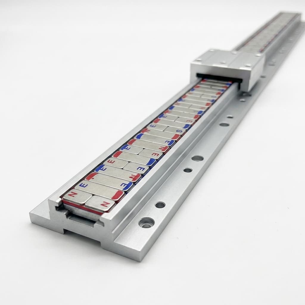
Product illustration of a track/carriage arrangement; not a measured field map or evidence of a qualified assembly.
A conventional alternating-pole track often uses steel back iron to redirect flux. A Halbach arrangement adds magnetization directions parallel to the track, strengthening one side and weakening the other. Finite arrays retain end leakage; Halbach geometry alone does not guarantee zero backside field. K&J Magnetics' Halbach overview demonstrates the principle and explains why the best configuration depends on the task.
In a four-block sequence, magnetization changes by 90° per block. A full magnetic wavelength λ contains four blocks; magnetic pole pitch τ is the distance between adjacent opposite vertical poles, so λ = 2τ. The sequence direction determines which side is stronger and must be shown on the approved drawing.
An ironless mover removes the toothed iron structure responsible for slot cogging. This does not mean zero force ripple or zero energized normal force. A slotless design can still contain iron, and attraction depends on the complete magnetic circuit. The Sun et al. motor model treats electromagnetic thrust and normal force for a particular ironless Halbach motor; its results are not ratings for every flat track.
Use Wavelength to Budget Air-Gap Variation
For an ideal periodic array, a useful first-harmonic approximation in the source-free air region is:
Bz(x, z) ≈ B0 × exp(−2πz / λ) × sin(2πx / λ)
B(z + Δz) / B(z) ≈ exp(−2πΔz / λ)
λ = 2τ
Here B0 is the fitted fundamental field amplitude at the reference surface, not the magnet material's remanence Br. Distance z includes the cover, potting above the magnets, and mechanical clearance to the evaluation plane. Finite length, width, iron, and higher harmonics require a fuller model.
Illustrative sensitivity calculation: with τ = 24 mm, λ = 48 mm, and an extra gap Δz = 0.15 mm, the fundamental field ratio is exp(−2π × 0.15 / 48) ≈ 0.981, a decrease of about 1.9%. This is a calculated field change, not measured thrust loss. Similar harmonic decay occurs in other periodic magnet structures; it is not exclusive to Halbach arrays.
Choose pitch jointly with the motor designer: winding layout, required force, coil heating, available gap, and drive voltage all matter. A larger pitch is not automatically more efficient.
3. The Modular Splicing Bottleneck: Physics of Track Seams
Long-stroke axes commonly assemble shorter carrier modules end to end. Module length is chosen around machining, handling, packaging, installation, and magnetic inspection constraints. There is no universal maximum magnet length or mandatory module size established by this guide.
At each joint, check three separate quantities: the carrier-to-carrier gap, the distance between magnetic pole centers, and the step in the working magnet surface. A dimensionally acceptable carrier joint can still have a reversed end block or a field-amplitude mismatch.
Modular Halbach Linear Track Splice Mechanics & Flux Continuity
Figure 1: Conceptual modular Halbach splice, not to scale or a simulated field map. Pole pitch τ is measured between opposite vertical poles, including across the seam. A datum controls assembly position; magnetic mapping checks the resulting field continuity. The sketch does not specify a manufacturing tolerance.
Mechanics of the Joint Phase Error
For a constant-pitch track, electrical angle advances by π radians per pole pitch:
θe = πx / τ
Δθe ≈ πΔτ / τ
The second expression estimates the phase change associated with a pole-center spacing error Δτ. It does not model the entire seam field or its interaction with a finite-length winding.
Illustrative calculation: τ = 24 mm and Δτ = 0.20 mm give Δθe = 0.0262 rad = 1.5°. In a sinusoidal, fixed-current projection model, the thrust ratio is cos(1.5°) ≈ 0.99966, a decrease of only 0.034%. That example does not establish severe thrust ripple, normal-force spikes, or controller windup. Local amplitude defects, coil overlap with the seam, current control, and structural response must be evaluated separately.
Splicing Architecture: Butt Joints, Stepped Joints, and Staggered Cartridges
- Referenced butt joint: Simple to manufacture and service. It can work when mounting datums, end-block spacing, and installation clearance are controlled. Ask for a scan through an assembled pair rather than rejecting this topology by name.
- Dowel-referenced or stepped joint: Helps establish repeatable module position. Fit, pin location, mounting torque, and thermal relief still need a tolerance stack; a dowel alone cannot guarantee magnetic phase accuracy.
- Staggered magnet cartridge: Separates the carrier joint from the magnet-cartridge joint. This may distribute a discontinuity, but does not eliminate magnetic end effects. Check replacement access and scan both joint types.
Buyer decision rule: qualify two joined modules in the intended mounting arrangement before approving a long run. Specify whether modules are interchangeable or supplied as a serialized matched set; replacement stock must follow the same rule.
4. Substrate Selection and Thermal Expansion Differential
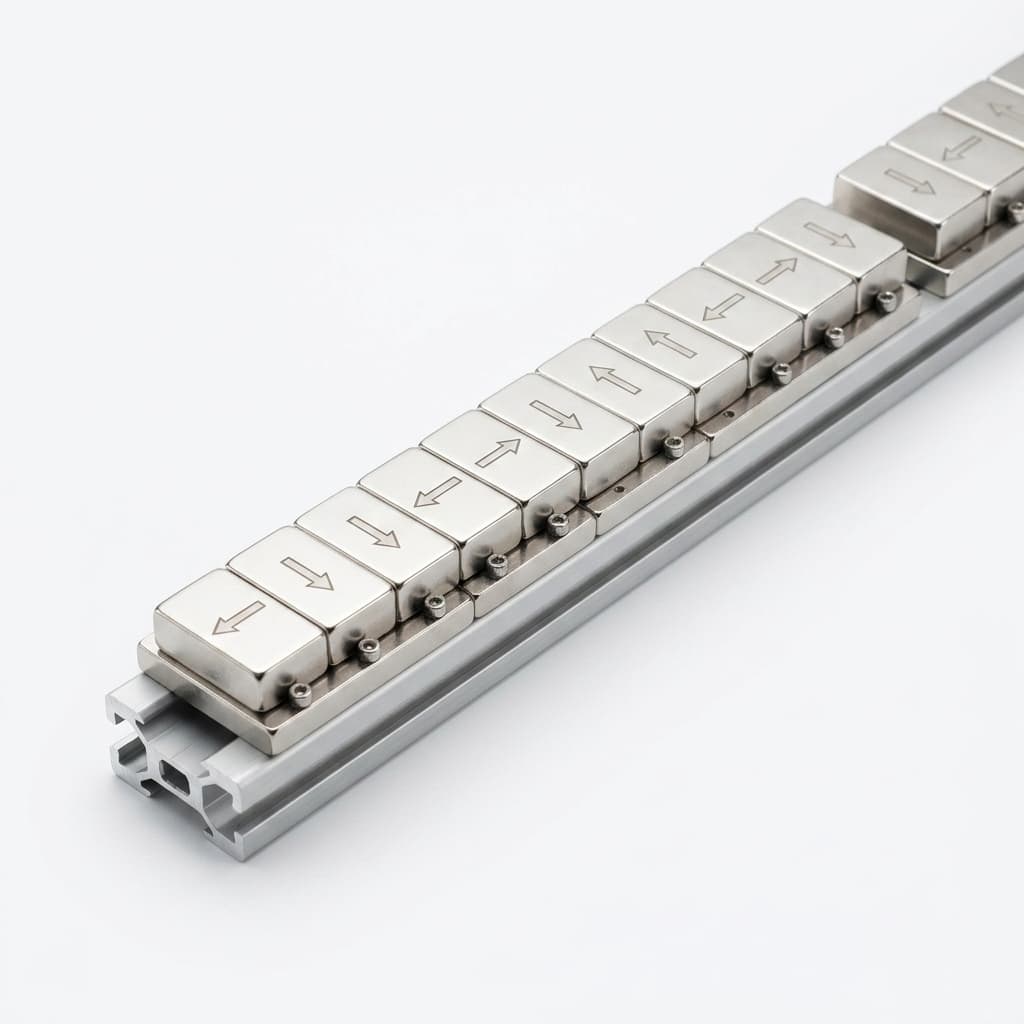
Product illustration for assembly context. Material grade, magnetization accuracy, and joint performance require inspection records.
Carrier selection changes stiffness, mass, corrosion behavior, magnetic interaction, and thermal growth. The following comparison is qualitative: request material certificates and temperature-dependent properties for the actual material condition.
| Carrier or assembly material | Selection reason | Constraint to resolve before ordering |
|---|---|---|
| Sintered NdFeB blocks | Supplies the permanent field | Expansion is anisotropic; each rotated block has a different orientation relative to the rail |
| 6061-T6 aluminum carrier | Low mass and machinability | Thermal growth relative to magnets and the machine bed; verify mounting restraint |
| 316L stainless steel carrier | Corrosion resistance and greater stiffness than aluminum | Added mass, thermal mismatch, and permeability after fabrication |
| Ti-6Al-4V carrier | Weight/corrosion trade-off for special environments | Cost, machining, thermal path, and qualified joining process |
| CFRP structure | Tailorable expansion and low mass | Layup-dependent expansion/stiffness, insert design, moisture, and electrical conductivity |
| Low-carbon steel backing or carrier | Can participate in the magnetic circuit | Changes flux distribution and attraction; requires electromagnetic and corrosion review |
A Free-Expansion Calculation Is Not a Bond-Stress Prediction
For a deliberately simplified calculation, assume a 1,000 mm aluminum strip with expansion coefficient 23.1 × 10⁻⁶/K, a continuous magnet strip with coefficient 3.5 × 10⁻⁶/K, and a uniform temperature rise of 40 K:
Aluminum free growth = 1000 × 23.1 × 10⁻⁶ × 40 = 0.924 mm
Assumed magnet free growth = 1000 × 3.5 × 10⁻⁶ × 40 = 0.140 mm
Difference in free growth = 0.784 mm
These are assumed inputs, not certified material values. A Halbach track contains separate, differently oriented blocks. At an assumed 20 mm bond length, the same coefficient difference gives 0.0157 mm of differential free growth. Actual adhesive stress depends on block length, bond thickness, restraint, shear-lag, creep, cure, and temperature gradients; dividing the full rail's free growth by a thin bondline does not establish that stress.
Adhesive and Thermal Qualification Questions
Ask for the adhesive datasheet, surface preparation, bondline control, cure record, and aged-strength data at your maximum assembly temperature. Do not select an adhesive solely by room-temperature lap shear or Tg, and do not assume a trade name meets a universal elongation or service-temperature limit.
Agree relief gaps and mounting constraints with the motor designer: they can accommodate expansion while also perturbing the magnetic field. Include environmental cycling, retention inspection, and post-cycle field checks appropriate to the real duty cycle. Stainless steel and CFRP do not automatically eliminate bowing or thermal mismatch.
5. Thrust Ripple Breakdown: Root Causes and Supplier Levers
State the ripple convention in the RFQ. One peak-to-peak definition is:
Thrust ripple (%) = 100 × (Fmax − Fmin) / |Favg|Use a nonzero average thrust and specify current, speed, load, temperature, measurement bandwidth, and travel interval. A percentage at zero mean is undefined; use force amplitude in newtons for unpowered detent tests. Field THD and thrust ripple are different measurements.
1. Magnet Strength and Orientation Variation
Block magnetic moment, dimensions, orientation, and assembly position can vary. Require polarity/orientation verification and define any sorting procedure against the assembled-field requirement. A magnetic-moment measurement is not automatically a direct measurement of remanence Br, so the supplier should state the method and uncertainty.
2. Spatial Harmonics and End Effects
Discrete blocks, finite ends, and seams change the field harmonics sampled by the winding. More segments or unequal magnet widths can improve a chosen design, but a four-to-eight-block change does not guarantee a fixed percentage reduction in motor ripple.
Liu et al.'s Halbach field study examines geometry changes and sinusoidal field quality. Its design-specific results support evaluating waveform shape; they do not establish universal seam, cost, or acceptance limits.
3. Motor and Control Contributions
Winding geometry, commutation offset, current ripple, encoder interpolation, cable forces, and mechanical friction can all contribute to measured motion error. If a force defect stays at a seam after swapping modules, investigate the installation datum and local gap. If it follows a module, inspect its field map and end sequence. Neither observation alone proves the root cause.
6. Comprehensive Selection Matrix: Linear Halbach Track Topologies
These seven procurement configurations overlap: a modular track can also be ironless or vacuum-compatible. Compare quotations at the same coil geometry, working gap, cooling, and duty cycle. Request force ratings in newtons under stated conditions and itemized quotations; flux density in tesla is not force density.
| Configuration | Why consider it? | Main integration trade-off | Evidence to request |
|---|---|---|---|
| Single-sided ironless Halbach | Open working face and no toothed-mover cogging | Gap control, energized normal force, and thermal load | Field map at coil plane; thrust/normal-force results with specified winding |
| Iron-core motor with Halbach secondary | Force-oriented design with a different magnetic circuit | Attraction, saturation, cogging, cooling, and bearing loads | Loaded electromagnetic model; force and detent tests |
| Double-sided ironless / U-channel | Two working faces around an ironless winding | Parallelism, assembly access, and bilateral force balance; not every U-channel is Halbach | Both magnetization drawings; gap and force-balance validation |
| Tubular Halbach | Cylindrical packaging and circumferential force symmetry | Bore alignment, end effects, radial clearance, and serviceability | Radial/axial field model and measured force curve |
| Vacuum-compatible encapsulated assembly | Controlled exposed materials for a specified environment | Outgassing, bakeout, seals, magnet temperature, and cover gap | Material/process records and environment-specific qualification |
| CFRP-supported assembly | Low moving mass or tailored expansion where justified | Layup, bonded inserts, thermal path, and mounting stability | Laminate properties; assembly thermal/mechanical validation |
| Long-stroke modular rail | Transportable sections and replaceable modules | Cumulative thermal growth, seam consistency, and replacement strategy | Joined-pair scans, serialized module map, and installed-axis acceptance plan |
Send your selected configuration and gap budget for an RFQ review. Include the required evidence in the quotation request so that supplier offers cover the same scope.
7. Factory Metrology & Quality Validation Protocols
A mechanical drawing and magnet-grade designation are insufficient to approve motion performance. Agree these inspection deliverables and acceptance limits before the purchase order; the methods below are a specification framework, not a published industry acceptance standard.
Protocol 1: Hall-Probe Field Mapping
- Define scan coordinates and the sensor's active-element height above the magnet reference face. Include cover thickness, temperature, probe calibration, orientation, and uncertainty.
- Scan individual modules and an installed pair across the seam. Record longitudinal position and the field components needed by the motor model, including transverse scan lines where winding width matters.
- Choose sample spacing from the shortest spatial harmonic of interest. For example, with λ = 48 mm, a seventh harmonic has a wavelength of about 6.86 mm; a 0.20 mm step supplies about 34 samples per cycle. This is an illustrative sampling calculation, not an inspection standard.
- Deliver raw position/field data, scan setup, fundamental amplitude/phase, and the harmonic-analysis window and bandwidth. Compare seam-region residuals with an agreed reference waveform; a full-track FFT alone can hide a local defect.
Protocol 2: Mechanical Datums and Pitch Measurement
Specify mounting face A, alignment shoulder B, magnet-face height, pole/block position references, and the temperature at inspection. A calibrated CMM or equivalent method can verify physical datums, but magnetic pole centers require magnetic measurements. Define seam gap, step, flatness, and pitch limits from the motor's error budget rather than copying a universal micrometer tolerance.
Protocol 3: Environmental and Motor-Level Acceptance
Qualify surface preparation, adhesive cure, mechanical retention, and protective covers against the agreed operating/storage temperatures, coolant or humidity exposure, and mounting loads. Select sample counts, dwell times, and cycle counts for the application. Inspect displacement and bond condition and repeat the field scan after exposure.
Finally, measure thrust and motion through the joint with the specified motor, current, speed, load, and controller settings. Hall mapping cannot by itself certify ripple, settling time, lifetime, or positioning accuracy. Retain the raw test conditions alongside pass/fail results.
8. The B2B Linear Halbach Track Procurement & RFQ Checklist
- Motor interface: State coil geometry, ironless/iron-core topology, pole-pitch convention, target thrust, speed, load, duty cycle, cooling, and operating temperature.
- Working field: Specify field components and waveform at the coil plane, including cover thickness and minimum/nominal/maximum clearance.
- Seam drawing: Define the end-pole sequence, datums, gap, surface step, pitch budget, mounting torque, and expansion strategy.
- Magnet qualification: Request grade traceability, temperature-dependent demagnetization data, polarity checks, and a documented sorting method where needed.
- Bond and retention: Agree surface preparation, adhesive/cure records, bondline control, mechanical retention, and environmental qualification.
- Protection: State corrosion, coolant, particulate, and handling exposure; validate cover material/thickness in the gap and thermal models.
- Inspection: Require raw Hall scans with uncertainty, joined-pair data, mechanical inspection results, and defined sampling coverage for production lots.
- Module replacement: Identify serialized order or demonstrated interchangeability, reference modules, spare-part policy, and installation instructions.
- Commercial acceptance: Compare tooling, inspection, packaging, shipping scope, lead time, warranty, and motor-level acceptance responsibilities in each quotation.
9. Frequently Asked Questions (FAQ)
What is the maximum practical stroke length for a modular Halbach linear motor?
There is no single stroke limit determined by Halbach magnetization. Establish it from module handling, cumulative expansion, mounting structure, encoder arrangement, cabling, drive segmentation, and installed test results. Adding modules does not guarantee unchanged performance; approve the full axis and its worst-case joint crossings.
Can we use standard commercial aluminum extrusions as the magnet carrier?
An extrusion can be a starting blank if subsequent machining, alignment, mounting, and inspection meet the drawing. As-extruded tolerances alone may be insufficient. Require measured datums and an installed gap budget; CNC plate, ground features, or a particular alloy are not mandatory for every motor.
How does an ironless U-channel track compare to a flat single-sided Halbach track?
A U-channel places the winding between two magnet rows and can balance normal forces in a symmetric design. It requires bilateral clearance and alignment. A flat track gives open access but has a different field and force balance. Not all U-channel motors use Halbach magnetization; compare actual magnetization patterns and measured force at the same current, temperature, and cooling. No universal performance ratio applies.
Why do suppliers quote different prices for the same linear track drawing?
Quotations may differ in magnet grade, carrier processing, quantity, sorting, adhesive qualification, test coverage, tooling amortization, packaging, delivery terms, and warranty. Ask suppliers to itemize these before interpreting a lower price as a quality problem. A drawing without a field and acceptance specification leaves substantial scope undefined.
How do we protect the track from steel chips and debris?
Assess covers, shielding, cleaning access, and an appropriate wiper or air-purge system with the machine designer. Cover thickness consumes magnetic clearance and conductive covers can introduce motion-dependent losses. Specify coolant compatibility and debris clearance; welding or bonding a cover must also be qualified for the magnet, coating, adhesive, and sealed environment.
10. Conclusion & Sourcing Next Steps
Approve a modular Halbach track against a shared mechanical drawing, an operating-gap field specification, a thermal/retention qualification plan, and motor-level acceptance criteria. A precisely located joint is useful evidence of assembly control; measured force and motion through that joint establish whether the axis meets its requirements.
For a sourcing discussion, send your coil drawing, travel length, pole pitch, nominal and worst-case gap, temperature range, duty cycle, required force/ripple definition, and annual quantity. Mark any unconfirmed requirement so it can be resolved before quotation.
- Explore Halbach array product options.
- Review application and integration options.
- Submit your drawings and RFQ checklist for a design review.
References & Authoritative Sources
Sources checked on October 26, 2026. These support the magnetic principles and design methods described above; the illustrative calculations and procurement framework are editorial analysis, not source-certified tolerances or first-party test results.
- Sun, Z., Jia, G., Huang, C., Zhou, W., Mao, Y., & Lei, Z. (2023). Accurate Modeling and Optimization of Electromagnetic Forces in an Ironless Halbach-Type Permanent Magnet Synchronous Linear Motor. Energies, 16(15), 5785. Supports analytical field/force modeling and geometry-specific optimization, not universal modular-joint limits.
- K&J Magnetics. Halbach Arrays. Supplier explanation and demonstrations of one-sided field concentration and practical assembly considerations; not a linear-motor acceptance standard.
- Liu, G., Hou, S., Xu, X., & Xiao, W. (2021). Design of a New 1D Halbach Magnet Array with Good Sinusoidal Magnetic Field by Analyzing the Curved Surface. Sensors, 21(7), 2522. Supports evaluating spatial harmonics and field-waveform quality for a specified geometry; not a guaranteed motor-ripple reduction.
Author

Categories
More Posts
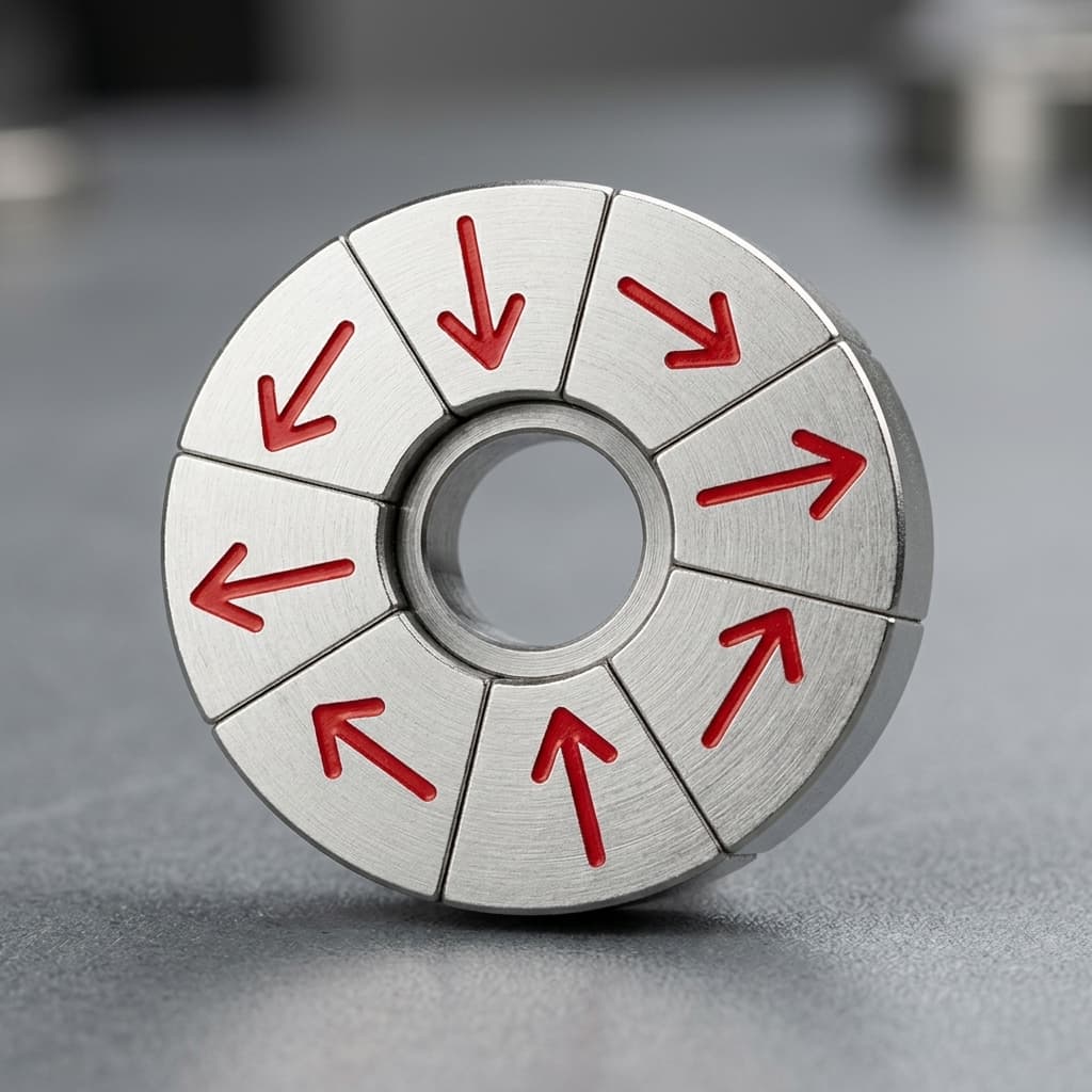
Halbach Array vs. Traditional Magnets: When to Choose Which
An engineering comparison between Halbach arrays and traditional multipole magnet rotors for BLDC motors, eVTOLs, and industrial applications.
Designing Halbach Cylinders for NMR, MRI, and Scientific Research
Learn how to achieve highly uniform dipole or quadrupole magnetic fields inside a bore using discrete Halbach cylinder assemblies.
Sourcing Custom Halbach Arrays from China: A Buyer's QA Guide
A procurement guide for sourcing precision magnetic assemblies. Learn how to validate OEM capability, 3D Gauss mapping, and angular tolerances.