
Halbach Array Voice Coil Actuators: Force Constant Linearity, Thermal Dissipation, and Precision Stage OEM Sourcing Guide
Source Halbach array voice coil actuators: compare force linearity, cooling, demagnetization risk, and supplier evidence. Get the OEM sourcing RFQ checklist.
A Halbach array voice coil actuator (VCA or VCM) is a direct-drive, non-commutated positioning device that uses spatially rotating permanent-magnet orientations to concentrate flux in the coil's working region. For precision stage OEM sourcing, compare force constant across the full stroke, heat at the actual duty cycle, and measured mechanical clearance before comparing peak force or price.
Halbach arrangements can increase working-gap flux and reduce backing-side leakage. The benefit depends on magnet volume, gap, winding geometry, temperature, and the reference design; the architecture alone does not establish a percentage improvement or a continuous-force rating.
Published: November 1, 2026. Last content and source review: November 1, 2026. Scope: Global OEM sourcing and preliminary engineering of planar, dual-opposed, and cylindrical Halbach voice coil actuators.
Limits: This guide provides a design-review method, illustrative calculations, and an RFQ template. It does not report first-party hardware tests, certify a supplier, or qualify a medical, cleanroom, or vacuum assembly. Numerical examples are assumed inputs, not product specifications. Project acceptance limits require agreement between the stage OEM and supplier.
Review the OEM RFQ specification checklist or contact our magnetic engineering team with your stroke, force-time profile, thermal envelope, and mechanical interfaces to discuss the review scope.
1. Executive Summary & Critical Sourcing Takeaways
- Compare motor constant and thermal path together.
Km = Kf / sqrt(R)describes force per square root of copper-loss power, in N/sqrt(W). A higher motor constant helps, but continuous force still depends on heat removal and permitted temperatures. - Budget the complete air gap. Include coil thickness, adhesive, magnet placement, guide runout, thermal growth, and dynamic frame deflection. Nominal clearance is not the minimum running clearance.
- Evaluate bobbin eddy currents in the actual field. A closed conductive former can dissipate energy when it encounters changing flux. Slots, higher-resistivity materials, or insulating formers have different thermal and structural costs.
- Check peak current at the magnet's worst temperature. A current multiplier or magnet grade suffix cannot establish demagnetization margin. Require temperature-dependent demagnetization curves and a local field assessment.
- Specify force linearity as an acceptance test. Request
Kf(x, T) = F/Iacross the usable stroke at agreed currents and temperatures, with a defined reference value and measurement uncertainty.
2. Electromagnetic Architecture: Lorentz Force and Motor Sizing Metrics
The Lorentz-force calculation integrates the vector cross product of current density and magnetic flux density over the conductor volume. For active wire perpendicular to a sufficiently uniform field, a useful scalar approximation is:
F = Bg × Lc × I = Kf × I
Kf = Bg × Lc
Pcu = I_rms² × R(T)
Km = Kf / sqrt(R(T))
Pcu = F² / Km²  (constant force, fixed Kf and R)
Here F is force in N; Bg is effective gap flux density in T; Lc is the summed active conductor length in m; I is current in A; and R(T) is winding resistance in ohms at the stated temperature. End turns contribute resistance without necessarily contributing thrust. Use the field integral for a nonuniform field or curved conductor geometry.
The Huang et al. Halbach VCA modeling paper is a relevant analytical-model reference. Its publication does not establish the field or force rating of a different supplier assembly.
Worked comparison: separate arithmetic from measured performance
Illustrative inputs: Both candidates have a 4-ohm winding at the comparison temperature, identical active conductor length, and a required constant force of 20 N. Assume candidate A has Kf = 10 N/A and candidate B has Kf = 17.5 N/A. These are hypothetical candidates, not catalogue ratings.
| Calculation | Candidate A | Candidate B |
|---|---|---|
| Force constant, Kf | 10 N/A | 17.5 N/A |
| Resistance at comparison temperature | 4 ohms | 4 ohms |
| Motor constant, Kf / sqrt(R) | 5 N/sqrt(W) | 8.75 N/sqrt(W) |
| Current for 20 N, F / Kf | 2 A | 1.143 A |
| Copper loss, I²R | 16 W | 5.224 W |
| Loss relative to A | 100% | 32.65% |
The assumed 75% increase in Kf at equal resistance yields a 67.35% reduction in copper loss. This is arithmetic, not a universal Halbach improvement: extra turns, different end-turn lengths, magnet mass, and hot resistance can change the result.
Thermal dissipation and drive voltage must close the sizing loop
For a separate illustrative duty cycle of 2 A for 25% of each cycle and 0.5 A for the remaining 75%, I_rms = sqrt(0.25 × 2² + 0.75 × 0.5²) = 1.090 A. At an assumed operating resistance of 4 ohms, average copper loss is 4.75 W. If the measured coil-to-sink thermal resistance were 8 K/W with a 35°C sink, a steady-state lumped estimate would give 35 + 4.75 × 8 = 73°C.
That estimate assumes a stable sink, an established thermal path, and cycles short relative to the relevant thermal time constants. It excludes bobbin losses and local hotspots. Resistance changes with temperature; a cold resistance value cannot be reused as a verified hot value. Request a temperature-rise test in the installed mounting condition, especially when vacuum removes convective cooling.
Also check amplifier voltage against resistive drop, L × dI/dt, and back EMF at maximum velocity. Peak current availability alone cannot establish acceleration bandwidth. Zhang et al. (2023) analyze a specific single-sided Halbach motor and water-cooling arrangements; those results illustrate why winding and cooling design must be evaluated together.
3. Structural Topologies: Planar, Dual-Opposed, and Cylindrical Halbach VCMs
Use the topology matrix to decide what evidence to request. These are qualitative design trade-offs, not guaranteed flux, stroke, cost, or cleanliness ratings. A non-commutated VCM must maintain the intended force direction over its usable stroke; a long alternating-pole track may instead require commutation or a different coil arrangement.
Table 1: Engineering Trade-Off Matrix for Halbach Array Voice Coil Actuator Topologies
| Engineering Metric | Single-Sided Planar | Dual-Opposed Planar | Cylindrical Moving-Coil | Cylindrical Moving-Magnet | Sourcing Verification |
|---|---|---|---|---|---|
| Working-gap field | Sensitive to coil distance from track | Two inward-facing strong sides can reinforce the gap field | Annular geometry requires radial field analysis | Field varies with shaft and winding geometry | Hall-probe map at the actual gap and temperature |
| Moving assembly | Flat coil and flex leads | Flat coil between tracks | Coil, former, and leads | Magnet assembly and retention hardware | Weighed moving assembly and cable-force budget |
| Stray field | End and lateral leakage remain | Reduced backing-side field; finite edges still leak | No automatic external shielding | Leakage depends on the full return geometry | Field map at actual encoder and sensor locations |
| Usable stroke | Coil/field overlap determines travel | Overlap and frame envelope constrain travel | Winding and active field lengths constrain travel | Shaft length and guides constrain travel | Measured force versus position over electrical stroke |
| Parasitic force | Ironless coil avoids tooth cogging | Inter-track loads require frame stiffness | Misalignment and nearby magnetic parts matter | Eccentricity can cause radial pull | Loaded deflection and side-force assessment |
| Assembly complexity | One track and exposed coil path | Opposing tracks require controlled assembly | Bore access and segment retention need review | Moving magnets require secure retention | Assembly tooling and inspection plan |
| Cleanroom or vacuum | Materials and exposed surfaces govern suitability | Narrow channels may complicate cleaning | Bore cleaning and winding outgassing matter | Coatings and guide wear require review | Material records, particle limits, and vacuum test plan |
The Jang et al. cylindrical moving-magnet paper addresses that specific architecture. Do not transfer its geometry or performance directly to a planar moving-coil design. An ideal centered, symmetric model can cancel lateral forces; manufacturing offsets and magnetic hardware break that symmetry.
4. The Coil Former Bottleneck: Eddy Current Damping & Material Selection
A conductive former can develop circulating currents when motion through spatially varying flux, or a time-varying field, produces a net electromotive force around a closed path. Motion in a uniform field does not by itself imply large eddy-current loss for every geometry.
A local low-speed model is F_drag = -c × v, with dissipated power P_drag = c × v², where c is in N·s/m. The coefficient must come from a geometry-specific electromagnetic model or measurement; it is not a universal material constant. At higher frequencies, the response can become frequency dependent.
Table 2: Engineering Comparison of Voice Coil Bobbin & Former Materials
| Former Material | Eddy-Current Consideration | Thermal / Structural Trade-Off | Supplier Evidence to Request |
|---|---|---|---|
| Solid aluminum | Closed conductive paths can support circulating currents | Useful heat spreading and low mass; drag depends on field geometry | Drag and temperature rise over the intended waveform |
| Slotted aluminum | A correctly placed slot interrupts selected current paths | Cuts change stiffness and heat flow; alloy resistivity is unchanged | Slot drawing, electrical continuity check, and structural analysis |
| Ti-6Al-4V titanium | Higher resistivity than aluminum can reduce currents; losses remain possible | Heat removal can be harder; geometry controls stiffness | Material certificate and coupled thermal/eddy-current analysis |
| PEEK | An insulating grade avoids bulk metal-like eddy paths | Heat flow, creep, fillers, and vacuum compatibility need review | Exact grade datasheet and hot dimensional test |
| Alumina ceramic | Electrically insulating grades suppress bulk circulating currents | Brittle; joints and thermal expansion mismatch can govern life | Assembly stress, shock, and thermal-cycle evidence |
| Self-supporting bonded coil | Removes former eddy loss, not winding loss | Bonding, winding retention, and thermal path become critical | Cure record, winding retention, and temperature-rise test |
RFQ decision: Require a drag budget at the actual velocity and frequency instead of imposing an unsupported universal frequency cutoff. Separate passive bobbin drag from electrical damping through the drive circuit; state whether the winding is open-circuit, shorted, or driven during the test.
5. Armature Reaction & Peak Pulse Demagnetization Boundaries
Peak current is an application input, not a fixed multiple of continuous current. Coil-generated fields can oppose local magnetization in parts of the assembly, with the worst location depending on current direction, coil position, and geometry.
Use supplier demagnetization curves at the magnet's worst operating temperature and evaluate the local field component along magnetization. Coil hotspot temperature and magnet temperature may differ. A scalar estimate based only on gap flux and ampere-turns cannot approve irreversible demagnetization margin.
Table 3: Evidence Required Before Approving a Magnet Grade
| Sourcing Condition | Candidate Discussion | Evidence Required | Acceptance Boundary |
|---|---|---|---|
| Moderate-temperature NdFeB design | Compare documented M/H grades if appropriate | Actual grade curves and magnet-temperature estimate | Room-temperature coercivity alone is insufficient |
| Higher thermal or reverse-field demand | Discuss SH/UH/EH grades with the vendor | Hot demagnetization curves and local operating points | Grade suffix does not approve a peak-current multiplier |
| High-remanence requirement | Consider grain-boundary-diffused material | Supplier process/grade data and part-size limits | Process name alone does not prove coercivity |
| Repeated peak pulses | Review pulse duration, polarity, and cooling interval | Coupled electromagnetic/thermal analysis over the waveform | Specify permitted permanent Kf loss after the agreed test |
| Vacuum or bakeout | Review magnets, coatings, adhesive, and winding together | Magnet temperature during bakeout and material records | Vacuum suitability is not implied by a high-temperature grade |
| Sm2Co17 alternative | Compare temperature stability, size, and retention needs | Grade-specific curves, brittleness controls, and cost | No assumption of zero thermal drift or radiation qualification |
Engineering requirement: Ask for a local demagnetization assessment at the worst combination of position, temperature, and current direction. Record assumptions and any allowed irreversible flux loss in the acceptance specification.
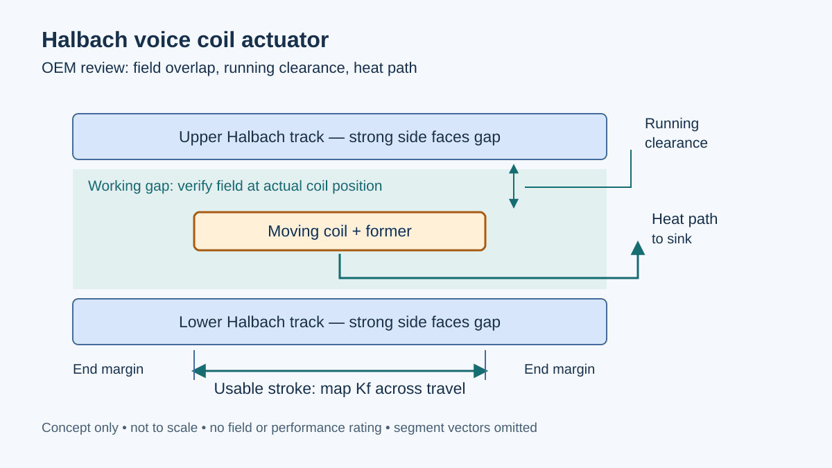
6. Technical Schematic: Dual-Opposed Halbach Flux Concentration
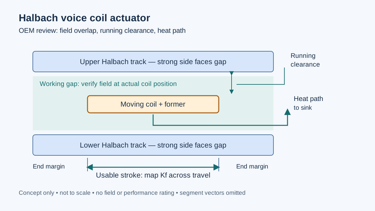
Figure 1: Conceptual procurement review diagram created for this guide, not a tested actuator or a magnetization assembly drawing. The strong sides face the working gap; segment vectors and local conductor directions require a design-specific field model.
In an air region, the vector contributions from both tracks superpose. Reinforcement requires the correct orientation and relative phase; a second track does not automatically double useful force. Finite segment size, ends, and nearby magnetic hardware affect both gap flux and external leakage. Non-magnetic aluminum plates are structural parts and do not guarantee magnetic shielding.
Specify the allowed field at each encoder or sensitive instrument, with coordinates and measurement conditions. Avoid a blanket claim of zero stray field or a universal safe standoff distance.
7. Fringe Fields, Stroke Limits, and Force Linearity Control
Finite-length tracks have end fields. What matters to the stage controller is the integrated force on the actual winding, not just the flux at one point.
- Underhung winding: The useful uniform-field region is longer than the coil. A preliminary overlap condition is
L_uniform >= stroke + L_coil; the physical track also needs end margins established by field modeling and force mapping. - Overhung winding: The coil is longer than the useful field region. Constant overlap can support nearly constant force, but inactive copper adds resistance and moving mass. This layout is not inherently the lower-weight option.
There is no universal 1.2-times-pole-pitch rule that guarantees linearity. For a reproducible acceptance test, define the reference Kf_ref, position grid including stroke ends, current, magnet and coil temperatures, and fixture friction compensation. Calculate 100 × (Kf(x, T) / Kf_ref - 1) at each point and compare it with the agreed tolerance. Repeat at relevant currents to detect current-dependent behavior.
Okyay et al. provide a voice-coil design and optimization reference. Use the supplier's own force map to establish the proposed stage's performance. If stroke-end gain variation or heat limits are unresolved, request a field and thermal review before freezing the mechanical envelope.
8. Manufacturing Tolerances, Assembly Jigs, and Cleanroom Packaging
Mechanical Air-Gap Tolerance Budget
Illustrative dimensional inputs: The magnet-face gap is 3.00 ± 0.05 mm and coil thickness including insulation is 1.60 ± 0.03 mm. Nominal centered clearance is (3.00 - 1.60) / 2 = 0.70 mm per side. At minimum gap and maximum coil thickness, centered clearance is (2.95 - 1.63) / 2 = 0.66 mm.
Now assume the drawing allocates an additional 0.10 mm to centering/runout, 0.08 mm to one-sided thermal growth, and 0.12 mm to dynamic deflection. The remaining worst-case clearance on the limiting side is 0.66 - 0.10 - 0.08 - 0.12 = 0.36 mm. These allocations are hypothetical; the example does not establish an acceptable clearance. Avoid counting magnet placement or adhesive variation twice if already included in the measured face-gap tolerance.
Assembly Fixturing & Bonding Chemistry
- Assembly fixtures: Require restrained assembly tooling and a supplier force/retention assessment. Loads depend on segment size and geometry; neither a generic force-per-segment claim nor a material label qualifies the fixture.
- Structural adhesive: Request the exact adhesive, cure schedule, bondline thickness, and joint-strength evidence at operating temperature. Room-temperature lap-shear data does not establish hot joint strength or fatigue life.
- Vacuum materials: NASA's outgassing database reports material testing under ASTM E595. It can support material screening, but ASTM E595 is a test method, not a complete assembly or UHV certification. Agree project TML/CVCM limits, cure conditions, and assembly-level vacuum tests.
- Coatings and packaging: Specify corrosion protection, adhesion, particles, cleaning, and packaging for the actual environment. A coating name or clean bag does not establish cleanroom classification or leak performance.
9. OEM Procurement & RFQ Engineering Checklist
Provide a force-time profile and an acceptance plan instead of an isolated peak-force number. The following checklist can be copied into an RFQ; blank limits are project inputs, not implied approvals.
HALBACH VOICE COIL ACTUATOR — OEM RFQ CHECKLIST

[ ] 1. Motion and mechanical envelope
    - Required continuous force: [ ] N under specified mounting/cooling
    - Peak force: [ ] N for [ ] ms, repetition interval [ ] ms
    - Full force/current-time waveform and dwell conditions: [attachment]
    - Velocity [ ] m/s; usable stroke [ ] mm; moving mass [ ] kg
    - Interface drawing, minimum running clearance, and cable routing: [attachment]

[ ] 2. Electrical and thermal limits
    - Bus voltage [ ] VDC; continuous current [ ] Arms; peak current [ ] A
    - Kf [ ] N/A at stated current and temperature; permitted variation [ ] %
    - Km [ ] N/sqrt(W); winding R [ ] ohms at [ ] degrees C; L [ ] mH
    - Maximum coil hotspot [ ] degrees C; magnet temperature [ ] degrees C
    - Sink temperature [ ] degrees C; mounting and cooling method [ ]

[ ] 3. Magnetic and environmental evidence
    - Exact magnet grade, coating, and temperature-dependent curves: [attachment]
    - Local reverse-field check at worst position/current/temperature: [attachment]
    - Permitted permanent Kf change after the agreed pulse test: [ ] %
    - Air / cleanroom particle requirement / vacuum pressure and bakeout: [ ]
    - ASTM E595 material records and project TML/CVCM limits if required: [ ]

[ ] 4. Former and structural evidence
    - Exact former material and slot/insulation drawing: [attachment]
    - Permitted passive drag [ ] N at velocity [ ] m/s; winding circuit state [ ]
    - Hot running-clearance budget and retention/adhesive records: [attachment]

[ ] 5. Factory acceptance and commercial handoff
    - Kf versus position/current/temperature map; grid and uncertainty agreed
    - Temperature-rise test using the specified duty cycle and mounting
    - Stray-field measurement at named sensor locations
    - Insulation/Hi-Pot method, voltage, and duration agreed for the insulation design
    - Material/lot traceability, cleaning, packaging, and inspection records
    - Prototype quantity [ ]; production quantity [ ]; lead time [ ]; change control [ ]
10. Frequently Asked Questions (FAQ)
What is the primary difference between a voice coil actuator and a linear motor?
A voice coil actuator is one type of linear motor. It usually uses a single non-commutated winding over a limited stroke; many longer-travel synchronous linear motors use multiphase commutation. An ironless VCM avoids tooth cogging, but force variation, friction, cable forces, sensor error, and control noise still limit positioning. Ironless commutated motors can also avoid tooth cogging.
Do Halbach arrays always outperform conventional voice coil magnets?
No. Halbach magnetization can concentrate working-side flux and reduce backing-side leakage, but a fair comparison holds the mechanical envelope, magnet volume, winding temperature, stroke, and cooling conditions explicit. Compare hot motor constant and measured force linearity; there is no architecture-wide percentage improvement.
How do I prevent high-frequency eddy current braking in voice coil bobbins?
Identify the changing flux and conductive loop paths first. A slot must interrupt the relevant path without being bridged by conductive joints. Higher-resistivity titanium or insulating formers may reduce loss, with different cooling and stiffness trade-offs. Verify drag over the operating waveform and separate it from drive-circuit damping.
Can a Halbach voice coil actuator operate inside an Ultra-High Vacuum chamber?
Potentially, after application-specific qualification. Review winding insulation, adhesive, coatings, trapped volumes, heat removal, and bakeout limits. ASTM E595 material data alone does not prove UHV compatibility; specify target pressure, contamination limits, residual-gas or outgassing tests, and the assembly bakeout procedure with the vacuum-system owner.
What causes force constant drop-off at the ends of the stroke?
Changing coil overlap and fringe fields can change the integrated field acting on the winding. The loss depends on geometry and cannot be assigned a universal percentage. Establish end margins with a model and verify Kf across the full usable stroke at agreed temperatures and currents; neither a fixed pole-pitch margin nor software calibration substitutes for that map.
11. Authoritative References & Scientific Sources
Sources checked November 1, 2026. The four DOI records identify relevant research; they do not validate this guide's hypothetical inputs or a supplier's product. The detailed cooling discussion below is supported by the second paper's published abstract. No proprietary measurements or customer outcomes are claimed here.
- Huang, X., Zhang, C., Chen, J., & Yang, G. (2019). Modeling of a Halbach Array Voice Coil Actuator via Fourier Analysis Based on Equivalent Structure. IEEE Transactions on Magnetics, 55(8), 1–6. DOI: 10.1109/TMAG.2019.2910780. Relevant to analytical Halbach VCA modeling; design-specific results require reading the full paper.
- Zhang, W., Zhang, H., Mu, J., & Wang, S. (2023). Design of a Single-Sided, Coreless, Flat-Type Linear Voice Coil Motor. Actuators, 12(2), 77. DOI: 10.3390/act12020077. The abstract describes magnetic-charge modeling, comparison with finite-element analysis, and two double-layer serpentine water-cooling plate configurations for a lithography application.
- Jang, S.-M., Choi, J.-Y., Lee, S.-H., Cho, H.-W., & Jang, W.-B. (2004). Analysis and Experimental Verification of Moving-Magnet Linear Actuator With Cylindrical Halbach Array. IEEE Transactions on Magnetics, 40(4), 2068–2070. DOI: 10.1109/TMAG.2004.832157. Relevant to the cylindrical moving-magnet topology; not evidence of a planar supplier product's performance.
- Okyay, A., Khamesee, M. B., & Erkorkmaz, K. (2015). Design and Optimization of a Voice Coil Actuator for Precision Motion Applications. IEEE Transactions on Magnetics, 51(6), 1–10. DOI: 10.1109/TMAG.2014.2381160. A precision-motion VCA design reference; no generic Halbach gain is inferred from its title.
- NASA Goddard Space Flight Center. Outgassing Database. Explains ASTM E595 testing and provides material-screening records; it does not certify complete actuators for UHV service.
12. Next Steps: Request a Custom Voice Coil Engineering Review
Use the completed checklist to compare suppliers on the same stroke, waveform, cooling condition, and evidence requirements.
- Explore our Voice Coil Actuators Solution Page for application and configuration discussions.
- Review our Linear Halbach Arrays Product Catalog for magnet-track options.
- Consult our Finite Element Analysis (FEA) Simulation Services to discuss field modeling and the validation evidence your project needs.
- Contact Our Engineering Team with your CAD envelope, force-time profile, and planned quantity to agree the next design and sourcing steps.
Author

Categories
More Posts
FEA Magnetic Simulation in Motor Design: How to Read a Flux Density Report
A practical guide for procurement and mechanical engineers on interpreting Finite Element Analysis (FEA) reports for magnetic assemblies and Halbach arrays.
Halbach Array Assembly Tolerances: Mechanical Precision vs. Magnetic Performance
Learn how Halbach array assembly tolerances affect flux, yield, and cost, with an RFQ decision matrix and supplier checks for precision magnetic builds.
Designing Halbach Cylinders for NMR, MRI, and Scientific Research
Learn how to achieve highly uniform dipole or quadrupole magnetic fields inside a bore using discrete Halbach cylinder assemblies.