
Halbach Array Magnetic Couplings: Torque Density, Containment Shell Eddy Losses, and OEM Sourcing Guide
Compare Halbach array magnetic couplings by torque density, containment shell eddy losses, and slip limits. Use an OEM RFQ checklist to request a design review.
A Halbach array magnetic coupling transmits torque without mechanical contact between its driving and driven rotors. Its rotating magnetization pattern reinforces flux on the working side and reduces flux on the backing side. For OEM engineers and buyers specifying sealless pumps, mixers, or vacuum feedthroughs, the useful comparison is hot pull-out torque across the complete containment gap, together with shell losses and fault recovery, rather than magnet grade alone.
Published: October 29, 2026. Last content review: October 29, 2026. Scope: Global OEM sourcing of synchronous, 1:1 permanent-magnet couplings in coaxial and face-to-face configurations. This is a literature-based procurement guide, not a report of tested product performance. Magnetic gears with flux modulators are discussed only as related research. Examples below are screening calculations; pressure approval, chemical compatibility, and protection settings require application-specific validation under the requirements of the installation country.
Review the procurement checklist, then request a coupling engineering review with torque, speed, temperature, fluid chemistry, and pressure-boundary requirements.
1. Executive Summary & Procurement Takeaways
- Compare torque density on the same basis. Halbach flux concentration can improve the useful field, but there is no universal percentage improvement. Compare the same gap, temperature, magnet volume, and complete assembly envelope, including retention and containment hardware.
- Separate torque from heat. A smoother air-gap waveform can reduce some harmonic losses. Increasing the fundamental flux can also increase eddy-current heating in a conductive shell. Require an electromagnetic and thermal comparison at the actual duty point.
- Select containment materials as a system. Electrical resistivity, wall thickness, corrosion resistance, pressure loading, joints, and cooling all affect the result. Carbon-fiber composites are electrically conductive and must not be assumed loss-free.
- Define slip protection before buying magnets. Pull-out limits transmitted torque, but sustained slip can heat magnets and nearby conductors. Require temperature-dependent demagnetization analysis and a validated detection and shutdown sequence.
- Make acceptance criteria contractual. Agree hot torque, runout, balance, leak-test method, and post-fault checks with the supplier. A generic grade suffix or a single leak-rate number does not qualify a coupling for your process.
2. Electromagnetic Architecture: Air-Gap Decay and Torque Generation
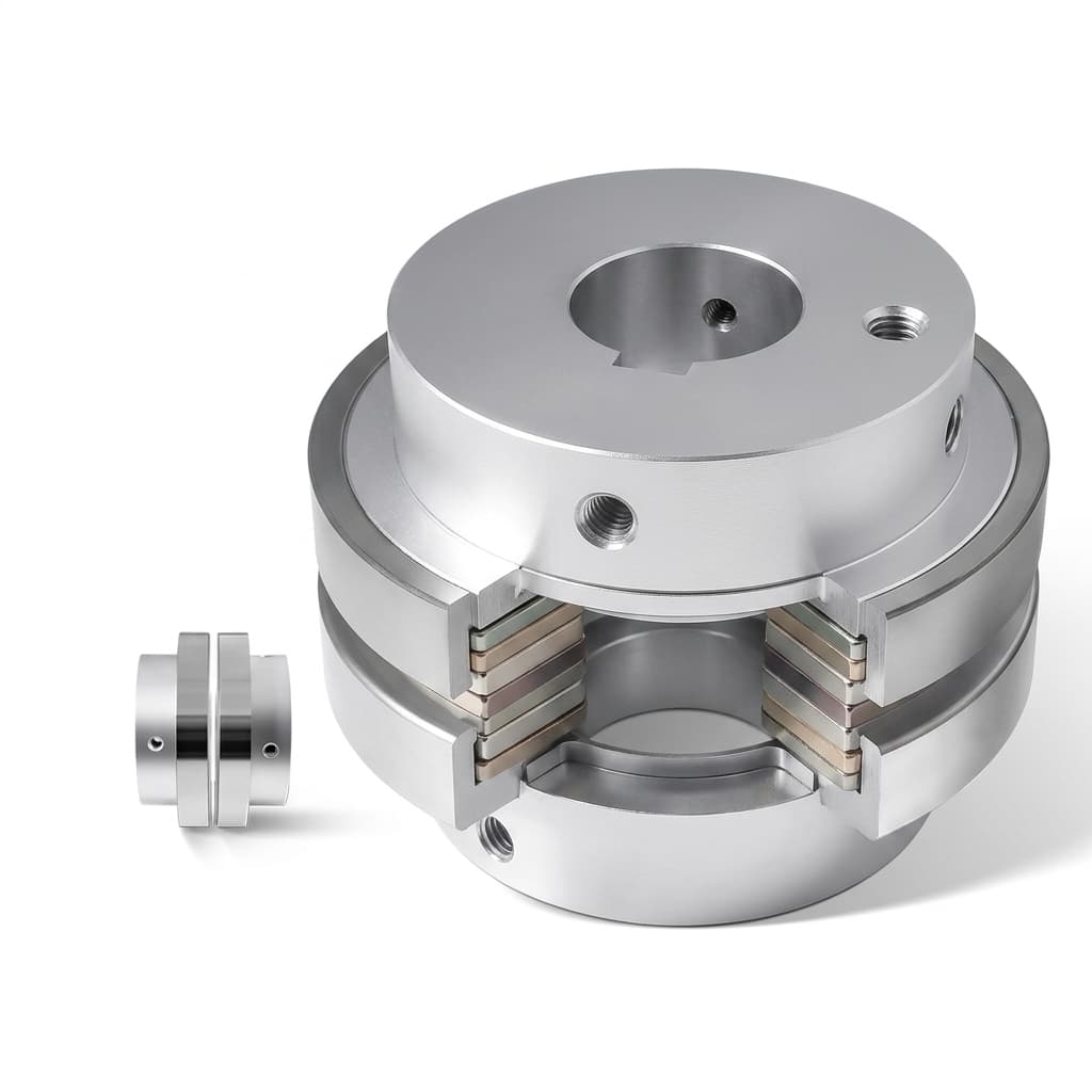
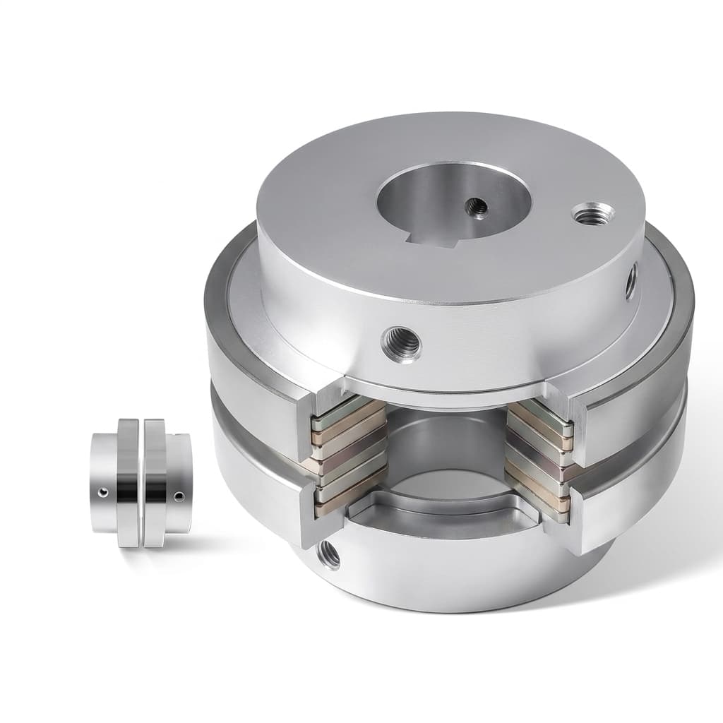
Figure 1: Catalog illustration of a magnetic coupling assembly. It explains packaging only; it does not establish magnetization direction, pressure rating, or measured torque.
A coaxial coupling uses nested cylindrical rotors. A face-to-face coupling uses opposing discs. Conventional arrangements alternate working poles; Halbach arrangements add intermediate magnetization directions to concentrate the field toward the opposing rotor. The exact vector sequence depends on geometry and which side should carry the field. Finite length, segmentation, and assembly tolerances leave residual leakage: self-shielding is not perfect cancellation.
Mathematical Torque and Air-Gap Scaling
For a coupling dominated by its fundamental spatial harmonic, a useful approximation is:
T(delta) ≈ T_pullout × sin(p × delta)
T ≈ 2π × R_gap² × L_active × mean(tau)
tau = B_radial × B_tangential / mu_0
Here p is pole-pair count, delta is mechanical load angle in radians, R_gap is the cylindrical integration radius, and L_active is active length. The mean shear stress mean(tau) is averaged over the integration surface. The last two expressions describe coaxial torque through Maxwell stress; they are not a way to infer torque from magnet remanence alone. Disc couplings require integration over the disc area and radius.
The ideal sinusoidal model peaks at p × delta = π/2. Harmonics, end effects, and misalignment can change the actual curve. Request a torque-angle curve rather than treating this approximation as a certified rating.
The non-magnetic path includes fluid clearance, stationary containment wall, outer running clearance, and any encapsulation jackets or sleeves between the magnets. For example, assumed clearances of 1.0 mm and 1.0 mm plus a 1.5 mm shell already give a 3.5 mm path before a rotor jacket is added. This is a geometry example, not a pressure-rated wall specification. Increasing pole count can make performance more sensitive to the gap; optimize pole pitch and magnet thickness together.
Li, Bird, and Acharya's radial coupling analysis derives ideal 3D torque equations and compares radial with axial Halbach couplings. Its idealized torque-density limits are useful for design reasoning, not a guaranteed improvement over a commercial conventional coupling. Li and Bird's axial model demonstrates why radial position and 3D fields matter for disc-coupling calculations.
Worked Procurement Example: Hot Torque and Package Volume
Assume a driven load needs 10 N·m continuously. An assumed driven inertia of 0.02 kg·m² accelerated at 100 rad/s² adds J × alpha = 2 N·m, giving 12 N·m during acceleration before other transient loads. A supplier's assumed minimum hot pull-out torque of 18 N·m gives a screening ratio of 18/12 = 1.5 against this demand. That ratio is not a universal service factor: add process peaks, tolerances, and the allowable load on the protected equipment before approval.
If the complete coupling fits a 100 mm diameter by 80 mm long cylindrical envelope, its envelope volume is π × 0.05² × 0.08 = 0.000628 m³. Continuous torque density is then 10/0.000628 ≈ 15.9 kN·m/m³; pull-out torque density is 18/0.000628 ≈ 28.6 kN·m/m³. Comparing one supplier's magnet-only peak value with another's complete-package continuous value would give a misleading result. These figures are reproducible arithmetic, not measured hardware data.
3. Coaxial vs. Face-to-Face Topologies
Choose the architecture from the pressure boundary, available envelope, and bearing loads before optimizing magnet grade. Table 1 compares two synchronous coupling layouts; it does not mix magnetic gears or linear actuators into their torque-density rankings.
Table 1: Engineering Trade-Off Matrix for Magnetic Coupling Topologies
| Procurement decision | Coaxial cylindrical coupling | Face-to-face axial disc coupling | Evidence to request |
|---|---|---|---|
| Available envelope | Nested rotors use radial space and axial overlap | Opposed discs require disc diameter and axial separation | Complete envelope drawing including bearings and guards |
| Containment geometry | Cylindrical cup between rotors | Flat or shaped diaphragm between discs | Pressure-boundary drawing, joints, and material condition |
| Magnetic bearing load | Symmetry can balance radial forces; eccentricity creates unbalanced pull | Axial attraction must be carried by the bearing arrangement | Force versus offset, gap, and load angle |
| Gap tolerance | Radial clearance, runout, and wall thickness govern the stack | Axial deflection, end float, and diaphragm thickness govern the stack | Worst-case tolerance and deflection analysis |
| Electromagnetic validation | Include finite axial length and end effects | Include radial field variation across the discs | 3D analysis and correlation with a torque test |
| Assembly and servicing | Nested magnets need controlled insertion and retention | Disc attraction requires controlled axial assembly | Assembly fixture, disassembly method, and handling instructions |
| Comparable quotation | Compare hot torque and losses in the full cylindrical package | Compare hot torque and losses in the full disc package | Same duty, temperature, volume definition, and FAT scope |
Neither topology has an inherent pressure rating or a fixed sourcing-cost multiplier. Pressure capability depends on the actual shell, joints, temperature, and loading; price depends on materials, segmentation, tooling, quantity, and inspection. An ideally concentric cylindrical model also does not prove zero axial force in a finite assembled machine.
4. The Containment Shell Bottleneck: Eddy-Current Losses & Thermal Limits
A stationary conductive shell sees a time-varying magnetic field even when the two rotors run synchronously. For a fundamental with p pole pairs at n RPM, its field frequency at the shell is f = p × n / 60. Magnet and shell temperatures therefore need review during normal operation as well as faults.
Figure 2: Catalog enclosure illustration. Internal rotor construction, weld quality, and balance cannot be inferred from this exterior view.
The Physics of Shell Eddy-Current Losses
For a thin conducting shell in a simplified regime, the following proportionality is useful for screening:
P_eddy ∝ B_gap² × omega² × t_shell / rhoomega is angular speed in rad/s, t_shell is shell thickness, and rho is electrical resistivity. This comparison holds geometry, current paths, field harmonics, and material temperature fixed and assumes weak shielding and negligible skin effects. It is not an absolute loss calculator. A conducting shell changes the field, and real cooling conditions determine the resulting temperature.
Under those assumptions, doubling speed gives four times the loss, and doubling resistivity halves it. If the field rises by 10%, speed by 20%, and wall thickness by 20%, the estimated loss ratio is 1.10² × 1.20² × 1.20 ≈ 2.09. Thus, even a useful increase in magnetic loading can coincide with a larger thermal burden. Obtain a coupled electromagnetic/thermal model or a validated loss test before selecting the can.
Table 2: Containment Shell Material Screening Matrix
This qualitative matrix is a request-for-evidence framework, not a material datasheet or a pressure/temperature rating. Obtain properties for the exact grade, product form, temperature, and chemical exposure.
| Material family | Electrical behavior | Potential sourcing reason | Constraint to resolve | Required supplier evidence |
|---|---|---|---|---|
| 316L stainless steel | Conductive; eddy loss must be evaluated | Fabrication and welded construction options | Corrosion, wall thickness, and heating in the actual fluid | Material certificate, compatibility assessment, loss model |
| Nickel alloy C-276 | Conductive; compare actual resistivity with alternatives | Candidate for some aggressive process fluids | Compatibility and weld procedure remain application-specific | Temperature-dependent properties, weld and corrosion evidence |
| Titanium Grade 5 | Conductive; not a loss-free barrier | Candidate where mass and chemistry favor titanium | Joining, fluid compatibility, and structural design | Material condition, joint procedure, thermal analysis |
| Zirconia ceramic | Electrically insulating for suitable grades and conditions | Avoid bulk metallic eddy-current paths | Brittle fracture, thermal shock, sealing, and proof testing | Grade-specific electrical/mechanical data and joint validation |
| Unfilled PEEK | Electrically insulating for suitable grades and conditions | Candidate for limited-temperature/pressure service | Creep, permeability, chemical exposure, and joint design | Long-term creep data and service-temperature limits |
| Carbon-fiber composite or carbon-filled PEEK | Conductive and direction-dependent | Candidate for structural tailoring or retention | Fiber paths, layup, and joints can support induced currents | Directional conductivity, layup, heating and pressure tests |
| Silicon carbide ceramic | Conductivity varies with grade and temperature | Candidate for selected chemical and wear environments | Do not assume electrical insulation; evaluate brittleness and joints | Exact-grade electrical data and validated assembly design |
What Halbach Harmonic Reduction Can and Cannot Establish
Mafi, Afjei, and Ghaheri (2021) study a Halbach magnetic gear, including waveform improvement and reduced modulator losses. Tzouganakis et al. (2024) study magnetic-gear torque and transient behavior. These are related mechanisms, but neither establishes a universal percentage reduction in containment-shell losses for a synchronous canned coupling. Ask for harmonic content and total shell loss in your actual geometry, rather than accepting a generic THD or efficiency claim.
If the shell material or wall thickness is still undecided, send the candidate materials and operating envelope for a design review before freezing the rotor diameter.
5. Structural Decoupling, Slip Torque & Thermal Runaway
When load demand exceeds available pull-out torque, the rotors can lose synchronism and pole-skip. This can limit transmitted torque, but it does not automatically provide safe fault operation or reliable re-engagement.
The Thermodynamics of a Jammed Impeller
The relative magnetic excitation at a rotor depends on speed difference:
f_slip = p × abs(n_driver - n_driven) / 60For four pole pairs, a 3000 RPM driver, and a stationary driven rotor, this frequency is 200 Hz. The stationary shell already sees the driver's rotating field during synchronous operation; a jam does not simply switch shell excitation from zero to full frequency. A jam also changes rotor-relative fields, torque oscillations, and process-fluid cooling. The resulting heat distribution needs transient analysis.
There is no universal time-to-damage or safe slip duration. Ask the supplier to model heat capacity, cooling, sensor location and delay, fault speed, and temperature-dependent magnet properties. Do not require an arbitrary continuous-slip test before an agreed test procedure establishes that it is safe for the assembly.
Sourcing Rule: Intrinsic Coercivity vs. Operating Temperature
Choose NdFeB or SmCo from demagnetization curves at the magnet's worst-case temperature and the opposing field during normal and fault conditions. Grade suffixes alone do not prove a safe operating point. SmCo can be a candidate when thermal stability is important, but it also requires grade-specific qualification; it is not insurance against all demagnetization.
Specify slip detection using a validated combination of speed/position feedback, process signals, and drive data. Motor current alone may not reliably identify decoupling. Agree shutdown time, restart interlocks, and cooling requirements from the fault analysis. Any temperature sensor or sensor well must preserve pressure-boundary integrity and have a response appropriate to the fault.
6. Manufacturing, Encapsulation & Mechanical Retention
Inner Rotor Encapsulation
For wetted NdFeB assemblies, justify the barrier against corrosion using the actual fluid, temperature, and exposure duration. Plating alone should not be treated as a hermetic pressure or chemical barrier. A corrosion-resistant jacket may be needed, with its thickness included in the magnetic gap.
Require material traceability, a qualified joining procedure, and control of the heat reaching the magnets and adhesive. There is no universal 150°C welding or machining limit for all magnet grades and assemblies. Review the grade's thermal history together with joint strength and sealing performance.
For helium leak acceptance, specify the method, pressure differential, tracer concentration, dwell time, calibration, background, units, and pass/fail threshold. Vacuum and sniffer methods have different practical sensitivity. An agreed helium test also does not replace pressure proof, corrosion qualification, or inspection of the pressure boundary.
Outer Rotor Centrifugal Retention
Halbach segment forces complicate assembly and adhesive loading. Validate the bond, sleeve or overwrap, hub, and magnet stresses at maximum operating and agreed overspeed conditions, including temperature and fatigue. Peripheral speed is v = π × D × n / 60; RPM alone does not define retention demand. Avoid a universal speed threshold for accepting adhesive-only retention.
Conductive metallic sleeves and carbon-fiber retention can also affect electromagnetic losses where time-varying fields exist. Include these parts in the relevant loss model and retain documented assembly and inspection procedures.
7. Factory Quality Control & Inspection Protocols
Use the following as a proposed FAT structure. Numeric tolerances and sampling must be agreed on the drawing or purchase specification, rather than adopted as industry-wide limits.
Protocol 1: Hall-Probe Field Mapping
Request field components around the rotor at a defined radius, axial position, temperature, and angular reference. Record probe calibration and scan spacing. Compare pole sequence, fundamental amplitude, angular phase, and harmonic content against the design model. A single surface Gauss reading cannot establish the complete working-gap field.
Protocol 2: Static Pull-Out Torque and Dynamic Fault Verification
Measure a torque-angle curve at the specified gap and temperature with a calibrated transducer. State minimum acceptable hot pull-out torque, uncertainty, and test-fixture compliance. Test acceleration and fault recovery separately under an agreed guarded procedure with defined speed, cooling, duration, stop criteria, and restart conditions.
If post-fault torque retention is required, compare before/after curves at the same temperature and gap. Torque retention within measurement uncertainty does not prove zero irreversible demagnetization. Do not substitute a room-temperature static test for a hot dynamic rating.
Protocol 3: Balance, Runout, and Traceability
Agree a balancing method and residual-unbalance limit based on rotor mass, speed, bearing arrangement, and machine requirements. Specify runout at the functional datums and confirm the minimum running clearance under deflection and thermal growth. Require serial numbers linking field maps, torque tests, material certificates, joining records, leak results, and balance records to the delivered assemblies.
8. OEM Procurement & RFQ Specification Checklist
Copy this checklist into the inquiry and ask suppliers to identify assumptions, exclusions, and unvalidated requirements explicitly.
- Operational duty: continuous and peak load torque, driven inertia, acceleration, reversals, speed range, and duty cycle.
- Torque acceptance: minimum hot pull-out torque, comparison temperature and gap, and required margin against the complete load profile.
- Thermal envelope: fluid and ambient temperatures, cooling flow and loss-of-flow condition, allowable shell loss, and magnet temperature limit.
- Geometry: coaxial or disc layout, full assembly dimensions, shaft interfaces, bearing loads, gap stack, jackets, and worst-case runout/deflection.
- Pressure boundary: operating and design pressures and temperatures, vacuum/external-pressure cases, installation jurisdiction, and applicable design requirements.
- Media compatibility: fluid composition, concentration, pH, solids, cleaning agents, and wetted-material/joint compatibility evidence.
- Containment choice: exact alloy, ceramic, or polymer/composite grade; wall thickness; joints; and electrical properties at service temperature.
- Magnet qualification: grade-specific demagnetization curves, load-line/fault analysis, thermal conditioning, and allowed irreversible change.
- Fault protection: detection signals, validated trip time, sensor response, cooling assumptions, and restart interlock; no assumed universal slip duration.
- Retention and sealing: stress/overspeed validation, joining qualification, agreed leak-test method and limit, and separate pressure-proof procedure.
- FAT records: field scan, hot torque-angle curve, dynamic test conditions, balance/runout, calibration uncertainty, and serialized traceability.
- Commercial scope: prototype and production quantities, tooling/NRE, lead time, change control, spare assemblies, and documents included in the quotation.
9. Frequently Asked Questions (FAQ)
What is the primary reason to specify a Halbach array over a standard magnetic coupling?
Specify it when a comparison at the actual gap and temperature shows useful torque or packaging gains. The rotating magnetization pattern can focus the working field, but it does not guarantee a fixed torque-density improvement or lower total shell loss. Include carriers, retention, and containment when comparing package volume.
Can a magnetic coupling completely eliminate pump seal maintenance?
It can replace a dynamic shaft seal at the coupling's pressure boundary with static containment. Static joints, containment shells, bearings, and process-fluid cooling still need inspection and maintenance. Neither zero leakage nor elimination of all VOC emissions follows from the coupling topology alone.
Why consider C-276 instead of 316L for a metallic containment can?
Compare exact-grade electrical resistivity and corrosion compatibility at the service temperature. Higher resistivity can reduce losses under otherwise equal conditions, but a different wall thickness, field, or cooling arrangement changes the result. Request pressure and loss calculations for both proposed cans; do not treat an alloy name as approval for a thinner wall.
What happens during direct-on-line motor starting?
The coupling must accelerate the driven inertia while supplying process load. If demand exceeds available pull-out torque, it can pole-skip. Check motor torque-speed data, driven inertia, and the acceleration trajectory. A VFD or soft starter may help, but it needs a ramp validated against both coupling torque and process-start requirements.
How can an OEM reduce demagnetization risk during a jam?
Use grade-specific hot demagnetization curves and fault modeling to select the magnets. Validate slip detection, shutdown timing, cooling, and restart interlocks with the supplier. There is no universal safe three-second, five-second, or thirty-second slip interval across different couplings.
When should an OEM compare SmCo with NdFeB?
Compare them when predicted magnet temperature, opposing field, or thermal stability makes the NdFeB option difficult to qualify. Assess actual grade curves, corrosion protection, retention, availability, and cost together. Maximum service temperature depends on the magnetic circuit and the whole assembly, not just the material family.
10. Conclusion & Sourcing Next Steps
A useful magnetic coupling quotation connects hot torque, complete gap geometry, shell loss, pressure containment, and fault protection in one agreed operating envelope. Halbach flux concentration is a design option; measured and modeled performance under those conditions is the purchasing evidence.
Before releasing drawings, ask the supplier to list unresolved assumptions and correlate its analysis with the agreed first-article tests. Use the Halbach product capabilities and magnetic coupling solutions to frame the assembly scope. The axial Halbach cost-factor guide can help separate materials, assembly, and tooling assumptions; it is not a coupling price list.
Submit your drawings and completed RFQ checklist for an engineering review, including candidate can materials and any unconfirmed pressure or fault requirements, so the discussion can focus on the evidence needed before a prototype order.
References & Authoritative Sources
Sources checked October 29, 2026. The two repository manuscripts were read directly. Publisher metadata and abstracts were available for the two DOI records; publisher full-text access was restricted. The gear papers provide related design context, not validated containment-shell loss data. Material certificates, pressure ratings, supplier performance, and acceptance limits are not established by these references.
- Li, Kang; Bird, Jonathan Z.; Acharya, Vedanadam M. Ideal Radial Permanent Magnet Coupling Torque Density Analysis. Manuscript hosted by DOE OSTI. Derives ideal radial Halbach coupling torque, validates the model against 3D FEA, and compares ideal radial and axial torque-density limits. Repository hosting does not imply DOE endorsement of a commercial product.
- Li, Kang; Bird, Jonathan Z. (2016). A 3-D Analytical Model of a Halbach Axial Magnetic Coupling. International Symposium on Power Electronics, Electrical Drives, Automation and Motion (SPEEDAM), pp. 1448–1454; manuscript hosted by NSF PAR. Supports 3D axial field/torque modeling and its assumptions, not a universal pressure or torque rating.
- Tzouganakis, P.; Gakos, V.; Kalligeros, C.; Papalexis, C.; Tsolakis, A.; Spitas, V. (2024). Torque Calculation and Dynamical Response in Halbach Array Coaxial Magnetic Gears through a Novel Analytical 2D Model. Computation, 12(5), 88. Analytical/FEA magnetic-gear comparison and transient slip context; gear results should not be transferred directly to synchronous 1:1 couplings.
- Mafi, H.; Afjei, E.; Ghaheri, A. (2021). Design of coaxial magnetic gear utilising a novel permanent magnet Halbach array structure. IET Electric Power Applications. The abstract discusses waveform, torque ripple, modulator losses, and prototype correlation. It does not quantify containment-can heating in a synchronous coupling.
Author

Categories
More Posts
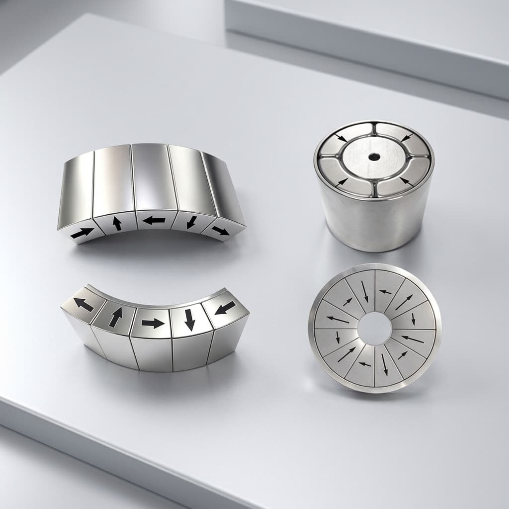
Understanding Neodymium Magnet Grades for High-Temp Rotors: N52 vs N42SH vs N38UH
A mechanical engineer's guide to selecting the correct NdFeB magnet grade for high-temperature operating environments to prevent irreversible demagnetization.
Designing Halbach Cylinders for NMR, MRI, and Scientific Research
Learn how to achieve highly uniform dipole or quadrupole magnetic fields inside a bore using discrete Halbach cylinder assemblies.
Halbach Array Linear Motor Tracks: Modular Pitch Splicing, Thrust Ripple Control, and Sourcing Guide
Source Halbach array linear motor tracks: compare splice designs, assess thrust ripple and thermal limits, and use the RFQ checklist to request a design review.