
Halbach Array Coaxial Magnetic Gears: Torque Density, Stationary Modulator Sizing, Eddy Loss Mitigation, and OEM Sourcing Guide
Source Halbach array coaxial magnetic gears: compare torque density, flux modulator designs, eddy current losses, and slip limits. Get the OEM RFQ checklist.
A Halbach array coaxial magnetic gear (CMG) transfers torque between concentric permanent-magnet rotors through a stationary ring of ferromagnetic pole pieces. For OEM sourcing, compare hot continuous torque, the volume used to calculate torque density, stationary modulator strength, two air-gap tolerance stacks, and losses during synchronous operation and overload slip before comparing unit prices.
Halbach magnetization concentrates flux toward a selected working region. Wong et al. (2023) report an experimental coaxial magnetic gear with 279 N·m/L torque density. Treat that figure as a result for the published prototype and its measurement basis. It is not a guaranteed continuous rating for an enclosed production gearbox, or evidence that every Halbach design outperforms a mechanical planetary gearbox.
Published and editorially reviewed: November 5, 2026. Scope: Global OEM sourcing of radial coaxial Halbach magnetic gears with a stationary modulator. The audience is procurement, mechanical integration, and application engineering teams comparing supplier proposals.
Limits: This guide provides a design-review framework, transparent sizing arithmetic, and an RFQ checklist. It contains no first-party dynamometer tests or supplier qualification results. The worked example uses assumed requirements, not measured hardware performance. It does not approve an assembly for hazardous areas, pressure containment, subsea service, or flight-critical applications; those require separate project qualification.
Use the OEM RFQ sourcing checklist, or request an application review with your torque profile, speed, cooling conditions, and available envelope.
1. Executive Summary & Critical Sourcing Takeaways
- Separate continuous torque from pull-out torque. Continuous torque requires an equilibrium temperature and stated cooling conditions. Pull-out torque is the coupling limit before loss of synchronism; it does not establish a sustainable operating point.
- Normalize torque density before ranking quotes. An active magnet-stack volume excludes bearings, end supports, seals, and housing. Require both active-volume and complete-assembly figures with dimensions and test conditions.
- Size the stationary modulator as a structural component. Its pole pieces carry time-varying flux, and its support reacts torque into the housing. Pole count alone cannot determine ring thickness, cage strength, or mounting bolt loads.
- Treat sleeve material as an electromagnetic and mechanical choice. A non-magnetic metal can still conduct eddy currents. Carbon-fiber composites also have direction-dependent electrical conductivity; neither material name establishes negligible loss.
- Agree on a tested slip response. Overload slip avoids tooth engagement failure, but can produce heating and torque oscillation. No universal trip time, safe slip duration, or automatic restart behavior applies to every magnetic gear.
These checks turn an attractive laboratory torque-density number into a procurement comparison with explicit operating boundaries. Require missing conditions to remain marked as unknown rather than accepting an unsupported rating.
2. Electromagnetic Architecture: Harmonic Field Modulation Principles
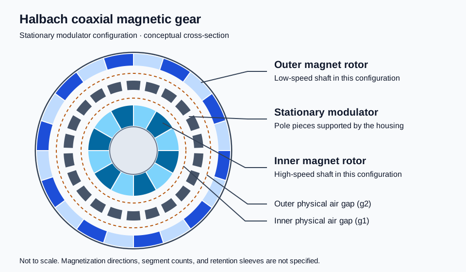
The inner and outer rotors have different pole-pair counts. The intermediate ferromagnetic ring modulates their spatial magnetic fields so that selected harmonics can couple and transmit torque. Jian and Chau (2010) describe a coaxial magnetic gear using Halbach permanent-magnet arrays; this is the relevant topology background, rather than a certification of any commercial part.
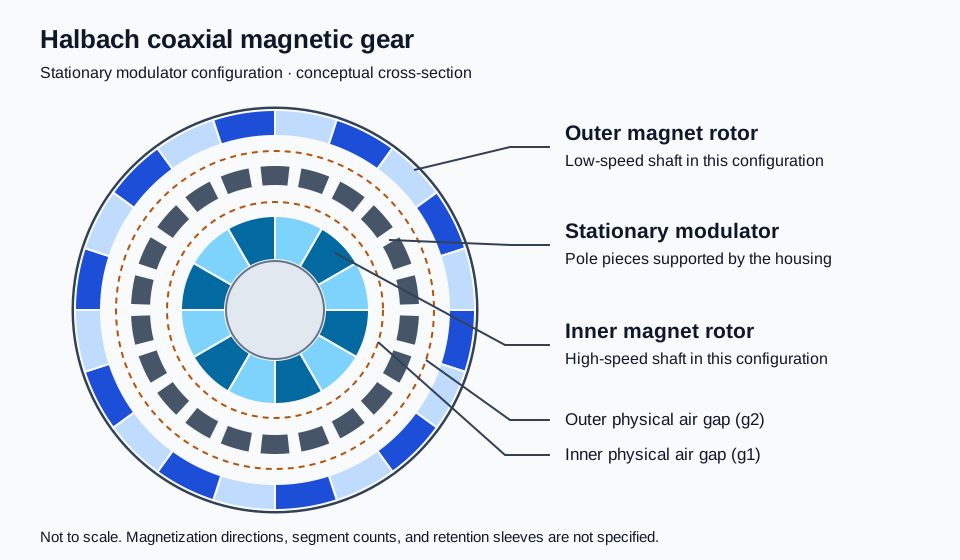
Concept diagram for this guide, not a manufacturing drawing or field simulation. Segment counts, magnetization directions, dimensions, and clearances must come from the supplier's design.
Pole Counts, Speed Ratio, and Housing Reaction
For the common sum-harmonic configuration discussed here:
n_s = p_in + p_out
p_in × omega_in + p_out × omega_out = 0   (stationary modulator)
omega_in / omega_out = -(p_out / p_in)
Here p_in and p_out are rotor pole-pair counts; n_s is the number of individual modulator pole pieces. Both angular velocities use the same positive direction. The minus sign means the rotors counter-rotate. These relations describe synchronous operation, not a slipping or accelerating transient.
Using positive input and output torque magnitudes at a steady operating point:
T_out = eta × (p_out / p_in) × T_in
P_out = T_out × abs(omega_out)
eta = P_out / P_in
Efficiency eta must be measured or explicitly assumed. It cannot be assigned from the Halbach label. For housing reaction, define signed external torques applied to the gear assembly separately: input torque, resisting load torque, and mounting reaction sum to zero at steady speed. Because the rotors counter-rotate, the applied input and resisting output torques have the same sign. The mounting reaction magnitude is therefore their sum under this simplified load case. Include acceleration, bearing loads, and fault conditions in the actual support calculation.
What Halbach Magnetization Changes
Rotating the magnetization direction around a rotor can concentrate the useful field and reduce the need for magnetic back iron. Practical segmented arrays still have leakage, end effects, manufacturing tolerances, and harmonics. Claims of complete flux confinement, zero leakage, or a fixed reduction in inertia need evidence for the proposed geometry.
Ask the supplier to compare designs at the same magnet volume, outer diameter, active length, air gaps, temperature, and retention requirements. Changing several of those at once prevents a fair attribution of improved torque to magnetization alone. Tzouganakis et al. (2024) present an analytical model checked against FEA and examine torque and transient response. Their model comparison supports a design-specific analysis, not a universal performance multiplier.
3. Engineering Sizing Relationships & Worked Calculation
Torque Density and Air-Gap Shear
State the volume definition beside every torque-density figure:
V_active_m3 = pi × R_out_m² × L_active_m
V_active_L = 1000 × V_active_m3
Torque density in N·m/L = T_out_Nm / V_active_L
Using metres in the first expression produces cubic metres. Omitting the conversion to litres creates a factor-of-1,000 unit error. Continuous and pull-out torque density must be reported separately, and active volume must not be silently substituted for the installed envelope.
For a cylindrical air-gap surface, a useful screening relationship is:
T = 2 × pi × r_gap² × L_active × tau_averagetau_average is the circumferential average of tangential electromagnetic stress at the operating angle. It is not the local peak stress. In a non-magnetic gap the local tangential Maxwell stress is B_radial × B_tangential / mu_0; integrating the field around the circumference gives torque. Peak radial flux alone cannot establish transmitted torque. Pull-out torque requires evaluating the torque-angle curve, with end effects and tolerances included where material.
Worked Example: A 10:1 Requirements Screen
Assumed requirements, not a customer case study: a winch concept needs 120 N·m continuous output at 300 rpm magnitude from a 3,000 rpm input. Assume an active diameter of 120 mm, an active length of 90 mm, and 97% efficiency solely for the arithmetic. An illustrative pull-out requirement of 180 N·m represents a buyer-selected margin of 1.5; it is not a design rule or an achieved result.
| Quantity | Input or calculated result | Procurement interpretation |
|---|---|---|
| Pole-pair and modulator counts | p_in = 2, p_out = 20, n_s = 22 | Establishes synchronous ratio; does not predict torque |
| Signed speed ratio | omega_in / omega_out = -10 | Output counter-rotates at 300 rpm magnitude |
| Active volume | pi × 0.060² × 0.090 × 1000 = 1.018 L | Excludes bearings, end plates, and housing |
| Required continuous torque density | 120 / 1.018 ≈ 117.9 N·m/L | Requirement at the specified hot operating point |
| Required pull-out torque density | 180 / 1.018 ≈ 176.8 N·m/L | Separate assumed acceptance target |
| Output mechanical power | 120 × 2 × pi × 300 / 60 ≈ 3.770 kW | Power delivered at the load shaft |
| Input mechanical power | 3.770 / 0.97 ≈ 3.887 kW | Based on assumed efficiency, excluding motor losses |
| Gear loss allowance | 3.887 - 3.770 ≈ 0.117 kW | Heat to account for if 97% efficiency is achieved |
| Required input torque | 120 / (0.97 × 10) ≈ 12.37 N·m | Steady running torque, excluding acceleration |
| Approximate mounting reaction | 120 + 12.37 ≈ 132.37 N·m | Continuous steady reaction; fault loads remain open |
This screen establishes what a supplier must demonstrate. It does not show that a Halbach rotor will meet the torque target inside that volume. The 117 W loss allowance must cover relevant magnet, sleeve, modulator, bearing, and seal losses under the same test boundary. A cooling calculation and instrumented thermal run are still required.
For quote comparison, ask each supplier to return measured or simulated values in a separate column, label the evidence type, and identify unverified requirements. A proposal with lower headline torque density may be preferable if it includes a complete housing volume, hot ratings, and traceable test results.
4. Architectural Comparison: Magnetic Gear Topologies
Use topology as a screening choice, then compare evidence under common conditions. The table deliberately avoids universal ratio or torque-density bands: magnet utilization, volume definitions, cooling, and manufacturability vary between designs.
| Topology | Potential reason to investigate | Main integration question | Evidence to request |
|---|---|---|---|
| Dual Halbach coaxial | Concentrate working flux on both rotors | Can the supplier assemble and inspect both arrays repeatably? | Magnetization map, torque-angle curve, retention drawings |
| Inner-rotor Halbach coaxial | Limit complex array assembly to one rotor | Does the outer rotor require back iron or added mass? | Matched-envelope comparison and loss model |
| Conventional surface-PM coaxial | Simpler magnet arrangement | How do back-iron saturation and inertia affect the duty? | Material curves, inertia, hot torque results |
| Axial-flux magnetic gear | Suit a short axial package | How are axial magnetic forces and disc deflection controlled? | Axial load analysis and minimum-gap stack |
| Transverse-flux or harmonic topology | Explore alternative ratios or packaging | Can a three-dimensional flux path be manufactured economically? | 3D analysis, tooling scope, assembly inspection plan |
| Spoke-type radial magnetic gear | Use flux concentration with radial magnet arrangements | How are magnets and pole structures retained under load? | Stress analysis, demagnetization assessment, rotor tests |
Application names such as subsea, aerospace, and cleanroom describe possible requirements, not automatic suitability. A magnetic gear still needs compatible seals, bearings, materials, and system qualification for the environment.
5. Stationary Modulator Sizing: Bridged vs. Discrete Pole Pieces
The stationary modulator is both a magnetic circuit and a load path. Set the pole count from the selected coupling relationship, then iterate radial depth, pole width, axial length, and support geometry against saturation, torque ripple, core loss, temperature, and deformation.
At a chosen mean radius r_s, the circumferential pitch is 2 × pi × r_s / n_s. This is the space available for a pole plus its separator or bridge, not a finished pole-width specification. Use the actual steel's magnetic and loss data at the relevant excitation conditions. More steel may improve stiffness while changing leakage and harmonic coupling.
For the mechanical review, convert reaction torque into forces at the actual support radius and trace them through pole retention, cage, end plates, and housing fasteners. Confirm that magnetic attraction and load-induced ovalization cannot close either air gap. A nominal ring diameter and pole count cannot establish that margin.
| Modulator construction | Possible advantage | Trade-off to resolve | RFQ evidence |
|---|---|---|---|
| Discrete laminated poles in resin | Removes continuous steel bridges between adjacent poles | Resin stiffness, creep, heat flow, and end support govern retention | Potting specification and hot deformation analysis |
| Bridged stamped laminations | Simplifies handling and stacking | Bridge geometry changes leakage and saturation; loss needs modelling | Bridge dimensions, insulation, FEA comparison |
| Composite-caged discrete poles | Can provide a light support structure | Fiber conductivity, resin temperature limits, and joints matter | Lay-up, electrical properties, thermal and structural analysis |
| Soft magnetic composite poles | May suit complex three-dimensional flux paths | Permeability, core loss, and mechanical strength differ from laminations | Frequency-dependent loss curves and strength data |
| Metal-caged discrete laminations | Provides a machinable mechanical support | Conductive cage paths can add eddy losses | Cage segmentation and harmonic-loss assessment |
| Solid steel poles | Simple prototype fabrication | Time-varying flux can create substantial core heating | Demonstrated loss and temperature at the intended duty |
Discrete poles remove a bridge leakage path; they do not eliminate all magnetic leakage or guarantee higher continuous torque. Likewise, no fixed percentage cost saving or torque penalty can be assigned to bridged laminations without a matched comparison. Require lamination thickness, coating integrity after machining, stack compression, and the method used to prevent electrical shorts between sheets.
If these construction choices are still open, send the competing modulator concepts for an application review with the common envelope and operating conditions so the comparison can focus on unresolved requirements.
6. High-Speed Rotor Retention Sleeves & Eddy-Current Mitigation
Magnet retention requires a structural assessment of speed, rotor diameter, magnet mass, assembly preload, temperature, fatigue, and overspeed conditions. A sleeve is one retention approach; its required wall thickness cannot be selected from speed alone. Agree the acceptance margin and overspeed procedure for the actual machine rather than adopting a generic safety factor.
Eddy currents arise from time-varying fields in the conductor's reference frame. Harmonic order, relative field frequency, geometry, segmentation, conductivity, and skin effect all matter. A rotor sleeve does not necessarily see the same spectrum as a stationary modulator. Ask for the loss distribution in each component under synchronous operation and fault slip.
| Retention material family | Reason to consider it | Loss or mechanical boundary | Required supplier evidence |
|---|---|---|---|
| Carbon-fiber composite | High directional strength and tailored lay-up | Conductive fibers can support eddy currents; resin and interfaces limit temperature | Directional conductivity, winding/preload model, thermal validation |
| Titanium alloy | Strength with higher resistivity than many structural metals | Still conductive; thickness and harmonic spectrum determine losses | Alloy condition, stress and eddy-loss analysis |
| Nickel-based alloy | Potential strength or environmental compatibility | Dense and conductive; suitability depends on alloy and heat treatment | Material certificate and coupled thermal assessment |
| Austenitic stainless steel | Available fabrication and corrosion options | Magnetic condition and eddy losses need checking after processing | Permeability, conductivity, retention and loss calculations |
| Glass-fiber polymer composite | Electrically insulating reinforcement option | Creep, moisture uptake, thermal expansion, and wall thickness matter | Environmental conditioning and long-term retention data |
| Aluminum alloy | Low mass and machinability | High conductivity can create substantial harmonic losses | Demonstrated loss budget and temperature at the proposed duty |
No material is universally the best sleeve or automatically prohibited at a particular rpm. Electrically insulating separators or segmented magnets may reduce some current paths, but require checking retention, balance, corrosion protection, and assembly complexity. Evaluate each mitigation against its effect on torque and manufacturing yield.
A non-magnetic sleeve inside the active gap adds magnetic separation even when the physical running clearance remains unchanged. Request a cross-section distinguishing magnet surface, sleeve, coating, adhesive, and physical clearance. Avoid counting sleeve thickness twice when a supplier already defines its effective magnetic gap from magnet surface to pole piece.
For each physical gap, document cold assembly clearance, bearing motion, radial runout, thermal differential growth, housing distortion, and dynamic deflection. Subtract the credible closing excursions from the nominal gap and retain a justified minimum clearance. Agree whether tolerances use worst-case or statistical treatment and provide inspection access for both concentric gaps.
7. Dynamic Overload Slip, Demagnetization Limits, and Thermal Protection
When load exceeds the available coupling torque, the shafts can lose synchronism. Slip can limit transmitted torque without meshing tooth failure, but the assembly may still experience fluctuating torque, heating, and loss of load control. It is not a substitute for a holding brake on a suspended load.
With a stationary outer rotor, a fundamental field-frequency screen is:
f_example_Hz = p_in × n_in_rpm / 60
For p_in = 2 and n_in = 3000 rpm: f_example = 100 Hz
Here n_in is speed in revolutions per minute, not angular velocity in radians per second. This example does not represent every harmonic seen by each component or predict a temperature rise. Transient losses, thermal mass, heat transfer, starting temperature, and event duration determine the outcome.
Contractual Protection Requirements
- Magnet operating point: Request grade-specific demagnetization curves at relevant temperatures, worst opposing field, magnet tolerances, and the method used to calculate irreversible loss. A grade suffix or advertised maximum temperature does not establish the assembly's safe operating temperature. Grain-boundary diffusion is a manufacturing option, not a universal requirement.
- Detection and shutdown: Agree how shaft speeds or positions reveal loss of synchronism, including a stalled output. A signed speed residual such as
p_in × omega_in + p_out × omega_outavoids dividing by zero at stall. Threshold, filtering, sensor faults, detection latency, drive response, and coast-down energy need validation together. - Slip duration: Establish the permitted event duration from the hottest credible initial condition using transient analysis and controlled testing. Specify repeat-event limits and cooldown conditions; do not copy a generic one-to-three-second limit into the contract.
- Restart: Define jam clearance, load holding, temperature confirmation, and a controlled resynchronization procedure. Do not assume that clearing a jam produces a safe automatic restart.
Emergency-stop behavior belongs to the machine-level risk assessment. Cutting drive torque can leave stored rotational energy and gravitational load motion. Test the complete stopping and holding behavior under the relevant load cases.
8. OEM RFQ Sourcing Checklist for Magnetic Gears
Attach this checklist to an RFQ and require the supplier to mark each item as confirmed, proposed, or unresolved. This keeps quotation assumptions visible before tooling or material commitments.
Mechanical & Geometric Specifications
- Ratio and direction: Pole-pair counts, modulator count, signed input/output speeds, continuous duty, acceleration, and permitted torque ripple.
- Dual air-gap budget: Drawings for both physical gaps, sleeves and coatings, runout, bearing motion, differential growth, and minimum hot clearance.
- Shaft and housing interfaces: Shaft fits, keys or splines, concentricity datums, mounting reaction, external radial/axial loads, and service access.
- Environmental boundary: Ambient range, process fluid, corrosion exposure, pressure differential, sealing method, and required qualification. An IP rating alone does not establish hermeticity or subsea pressure capability.
Magnetic Materials & Modulator Architecture
- Magnet specification: Grade, magnetization direction and tolerance, temperature-dependent curves, segmentation, adhesive, and retention method.
- Corrosion protection: Coating system, thickness, adhesion inspection, and agreed environmental testing. Salt-spray exposure alone does not predict service life.
- Modulator construction: Steel or composite grade, pole dimensions, lamination thickness and insulation, bridge geometry, cage material, and assembly process.
- Rotor retention: Material properties, preload, speed range, temperature range, fatigue assumptions, and agreed overspeed acceptance evidence.
Thermal, Efficiency & Overload Protection
- Thermal rating: Cooling conditions, mounting heat paths, duty cycle, component temperature limits, and measurement or estimation method for inaccessible magnets.
- Continuous versus pull-out torque: Guaranteed values at stated temperatures, margin rationale, torque-angle curve, and volume definitions for density claims.
- Slip response: Detection method, worst-case latency, permitted event energy and duration, repeated-event limits, cooldown, and restart sequence.
Factory Acceptance Testing & Quality Records
- Torque-angle measurement: Fixture, sensor calibration, test temperature, speed or static procedure, uncertainty, and minimum acceptance value.
- Dynamic efficiency map: Agreed speed/load points, thermal stabilization criterion, shaft measurement locations, loss boundary, and uncertainty.
- Magnetic inspection: Magnetization direction checks, agreed Hall-probe mapping geometry, traceable serial numbers, and nonconformance handling.
- Balance, vibration, and noise: Rotor balance criterion and applicable standard edition, assembly vibration limits, mounting condition, sensor locations, and acoustic background.
Do not release a production order while guaranteed performance and proposed simulations remain indistinguishable. Separate non-recurring engineering, fixtures, prototype quantities, production pricing, inspection scope, lead time, change control, and ownership of design/test records in the commercial response.
9. Frequently Asked Questions
What is the primary advantage over a mechanical planetary gearbox?
Torque crosses an air gap without meshing gear teeth, which can reduce tooth wear and remove gear-mesh lubrication from the torque path. The complete assembly still contains bearings, and may contain seals or cooling systems that need service. Claims of zero maintenance, zero particles, or cleanroom suitability require evidence for the assembled machine.
Can a magnetic gear replace a cycloidal or harmonic drive in precision robotics?
Only after comparing stiffness, positioning behavior, inertia, ratio, envelope, thermal duty, and fault response. A magnetic coupling has finite torsional compliance even without tooth-clearance backlash. Check the torque-angle slope and dynamic response with the actual controller and load; a torque-density figure alone cannot establish positioning accuracy.
Why do quotes differ between bridged and discrete modulators?
Bridged laminations can simplify handling, while discrete poles require a separate retention structure. Bridges change magnetic leakage and saturation, and supports introduce their own loss and heat-flow paths. Ask for a matched design comparison and itemized tooling/assembly costs rather than assuming a fixed torque penalty or labor saving.
What happens during an emergency stop?
Deceleration torque may exceed coupling capacity and cause slip. Shaft behavior then depends on inertia, load, brake arrangement, and drive response. Verify stopping distance, load holding, transient temperature, and restart conditions at machine level. Magnetic slip is not an independently qualified emergency-stop function.
How does temperature affect torque capacity?
Temperature changes magnet properties, opposing-field margin, material dimensions, and heat transfer. Use component temperatures rather than ambient temperature alone, and request hot torque and demagnetization evidence. A percentage change in magnet remanence cannot be applied directly as an identical percentage change in gearbox torque without a magnetic model.
Do both rotors require balancing?
Balance and runout requirements should follow rotor mass, speed, support stiffness, gap clearance, and the agreed machine standard. The high-speed rotor often drives a tighter requirement, but generic balance grades cannot qualify every assembly. Verify installed vibration and minimum dynamic clearance as well as individual rotor balance records.
10. Conclusion & Sourcing Next Steps
A useful magnetic gear specification connects hot continuous torque, pull-out margin, stationary modulator reaction, dual-gap clearance, retention losses, and validated slip response. The worked example provides a reproducible requirements screen; supplier analysis and hardware testing must establish the final rating.
Review our magnetic gear application and OEM sourcing overview and custom Halbach assembly capabilities to frame the manufacturing discussion. For a cost-breakdown method, the Axial Halbach Cost Factors Guide covers magnet, tooling, assembly, and inspection inputs. Its axial geometry and user-entered estimates are not a coaxial magnetic gear quotation.
Submit your torque profile and envelope for an application review. Include continuous and peak load, input speed, cooling, environment, installation constraints, annual quantity, and required acceptance records so unresolved assumptions can be identified before a formal quote.
References & Authoritative Sources
Bibliographic metadata checked against the DOI records on November 5, 2026. These peer-reviewed sources establish relevant prototype and modelling context; they do not certify this guide's illustrative requirements, a supplier's manufacturing capability, or universal material limits.
-
Wong, H. Y., Baninajar, H., Dechant, B. W., Southwick, P., & Bird, J. Z. (2023). Experimentally Testing a Halbach Rotor Coaxial Magnetic Gear With 279 Nm/L Torque Density. IEEE Transactions on Energy Conversion, 38(1), 507–518. The reported prototype torque-density benchmark is a literature reference, not a guaranteed hot continuous rating for an installed assembly.
-
Jian, L., & Chau, K. T. (2010). A Coaxial Magnetic Gear With Halbach Permanent-Magnet Arrays. IEEE Transactions on Energy Conversion, 25(2), 319–328. Relevant background for the Halbach coaxial architecture; use project-specific analysis for field strength, loss, and torque predictions.
-
Tzouganakis, P., Gakos, V., Kalligeros, C., Papalexis, C., Tsolakis, A., & Spitas, V. (2024). Torque Calculation and Dynamical Response in Halbach Array Coaxial Magnetic Gears through a Novel Analytical 2D Model. Computation, 12(5), 88. Describes an analytical model checked against FEA and examines torque and transient slip response. Model results do not replace prototype thermal or fault testing.
Author

Categories
More Posts
Halbach Array Segment Count: 4 vs 8 vs 16 Blocks (Cost & Performance)
Compare Halbach array segment counts across 4, 8, and 16 blocks: flux, ripple, eddy-current risk, cost drivers, QC checks, and RFQ guidance.
FEA Magnetic Simulation in Motor Design: How to Read a Flux Density Report
A practical guide for procurement and mechanical engineers on interpreting Finite Element Analysis (FEA) reports for magnetic assemblies and Halbach arrays.
Designing Halbach Cylinders for NMR, MRI, and Scientific Research
Learn how to achieve highly uniform dipole or quadrupole magnetic fields inside a bore using discrete Halbach cylinder assemblies.