
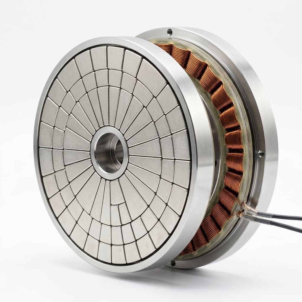
Axial Flux Halbach Array Rotors: Dual-Rotor Topologies, Slotless PCB Stator Air-Gap Sizing, Axial Attraction Balancing, and OEM Sourcing Guide
Compare axial flux Halbach array rotors for OEM sourcing: define PCB stator gaps, axial loads, magnet segmentation, and acceptance tests. Prepare a rotor RFQ.
Axial flux Halbach array rotors are an option for OEMs seeking a thin motor package with a coreless winding. For procurement, the first decision is whether the complete rotor pair can meet the working-plane flux target across the actual stator thickness while retaining sufficient mechanical clearance. A high surface Gauss reading alone cannot answer that question. Axial flux permanent magnet (AFPM) machines direct their working flux parallel to the shaft across an annular gap; radial-flux machines use a cylindrical working gap.
An ironless coreless stator, such as a printed circuit board (PCB) winding or an encapsulated air-core winding, removes stator iron losses and tooth-related cogging. Copper, magnet, carrier, bearing, and inverter losses remain. The magnetic gap includes the winding thickness as well as both mechanical clearances. Conventional alternating-pole surface permanent magnets (SPM) remain a valid baseline: compare them with Halbach rotors at equal magnet volume, temperature, working gap, and structural envelope before paying for additional magnet orientations.
In a dual-rotor Halbach topology, spatially rotating magnetization can concentrate flux toward the winding and reduce backside leakage. The benefit depends on pole pitch, segmentation, magnet thickness, and gap; no universal percentage gain is assumed here. Hong, Park, and Jeong compare SPM and Halbach configurations in a dual-rotor machine with an iron-cored segmented armature. Their study provides topology and structural context, but its results are not direct validation of a coreless PCB motor.
Yet for procurement managers and mechanical system architects, sourcing custom axial-flux Halbach rotors involves critical manufacturing risks: multi-kilonewton axial attraction forces that threaten bearing reliability, high-frequency rotor eddy-current heating, sub-millimeter runout tolerances, and dynamic balancing hurdles. This technical guide outlines the electromagnetic physics, back-plate material trade-offs, magnet segmentation rules, quality control testing, and a comprehensive RFQ framework for sourcing production-grade axial-flux Halbach rotor assemblies.
Published & Reviewed: November 8, 2026. Scope: Global OEM procurement of permanent magnet rotor assemblies for dual-rotor coreless and slotless axial flux machines.
Here, the gap examples apply to fully ironless stators. A slotless winding with an iron back-core needs a different magnetic and axial-force model. This is a sourcing decision framework with illustrative calculations, not a report of our hardware tests or certification for aircraft use. Material selection and acceptance limits must be agreed for the actual assembly.
Preparing a supplier comparison? Use the RFQ checklist below, then request a rotor design review with the stator stack, speed range, and duty cycle.
1. Executive Summary & Procurement Takeaways
- The Coreless Magnetic Air-Gap Reality: In an ironless or PCB-stator axial flux motor, the effective magnetic gap (
g_m) is not the mechanical clearance alone. It equals the sum of the drive-side clearance (g_1), the central stator thickness (t_stator), and the non-drive-side clearance (g_2). A clearance value alone cannot define this gap; the example below uses 0.8 mm on each side of a 2.4 mm stator. Never qualify magnets based on surface Gauss; mandate working-plane flux density (B_z) mapped at the exact stator copper centerline. - Separate Rotor Clamping from Bearing Thrust: Opposing rotors can exert substantial mutual attraction even with an ironless stator. The load passes through the carrier, hub, spacers, and bearing arrangement according to the assembly design. Moving a non-magnetic stator within a fixed rotor gap does not by itself establish an unbalanced magnetic bearing load. Specify disc deflection, assembled runout, thermal growth, and minimum operating clearance together.
- Coreless Motors Still Have Magnet Eddy Losses: Winding spatial harmonics and PWM ripple can induce currents in conductive magnets and carriers. Segmentation is a candidate mitigation, but its direction, number of cuts, and electrical isolation must follow the predicted rotor-frame loss distribution and thermal validation.
- Reduced Backside Flux Can Enable Lighter Carriers: A Halbach layout may permit a non-magnetic structural plate. Finite arrays still leak flux, and the plate must carry magnetic and centrifugal loads. Compare total inertia, deflection, thermal behavior, and manufactured cost rather than assuming a fixed mass-saving percentage.
- Contractual Acceptance Must Be Multi-Dimensional: Mechanical CMM data cannot detect reversed magnetization or incorrect pole phase. Agree working-plane Hall maps, magnet batch records, assembled runout, balance reports under ISO 21940-11 where rigid-rotor behavior applies, and representative bond qualification. Balance grade and sampling frequency are application-specific.
2. Electromagnetic Architecture: Dual-Rotor Halbach Topologies
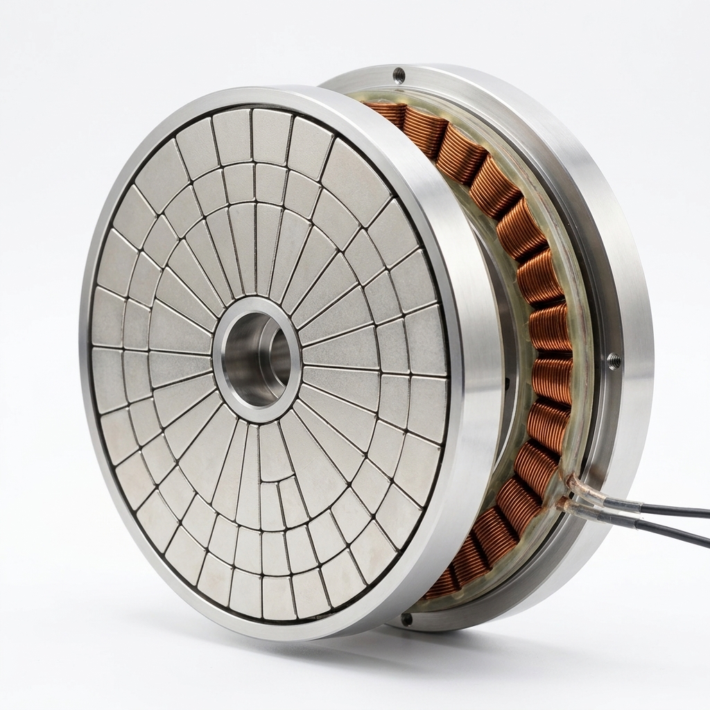
Illustrative axial-flux assembly image showing an annular magnet face and copper windings. It does not establish the internal magnetization sequence, core material, or measured performance.
2.1 The Physics of Axial Flux Concentration
In an AFPM machine, radial conductor current interacts with axial flux to produce tangential force. A dimensionally consistent starting point is to integrate the tangential shear stress over an annular torque-producing surface:
T_e = 2π ∫[R_in to R_out] τ_t(r) · r² drHere τ_t is the time-averaged tangential stress in N/m² and the radii are in meters, giving torque in N m. For an illustrative uniform stress, T_e = (2π/3)τ_t(R_out³-R_in³). A winding model must supply the stress from its current distribution, winding factor, and field waveform. Count each physical torque contribution once; a dual-rotor layout does not justify doubling an already combined-field calculation.
Iron teeth can guide flux in a slotted machine. A coreless design instead needs a field solution across the entire non-magnetic stack; neither rotor type has a universal working flux density.
In a coreless / PCB-stator configuration, the non-magnetic region consists of:
g_m = g_1 + t_stator + g_2For an illustrative stack with mechanical air gaps g_1 = g_2 = 0.8 mm and a multi-layer rigid PCB stator substrate thickness t_stator = 2.4 mm, the effective magnetic gap is g_m = 4.0 mm.
For these example inputs, the stator mid-plane is 2.0 mm from either magnet face, not 0.8 mm. Report the probe origin and copper-layer locations. A single-rotor map at the nearest winding surface cannot substitute for a matched-pair field map or validated superposition model.
RFQ gap example (illustrative, not a tested motor):
Rotor 1 magnet face -> g1 = 0.8 mm -> stator = 2.4 mm -> g2 = 0.8 mm -> Rotor 2
Total non-magnetic gap: 4.0 mm; winding mid-plane: 2.0 mm from either magnet face.
Include coatings, potting, and covers if they are outside the stated stator thickness.
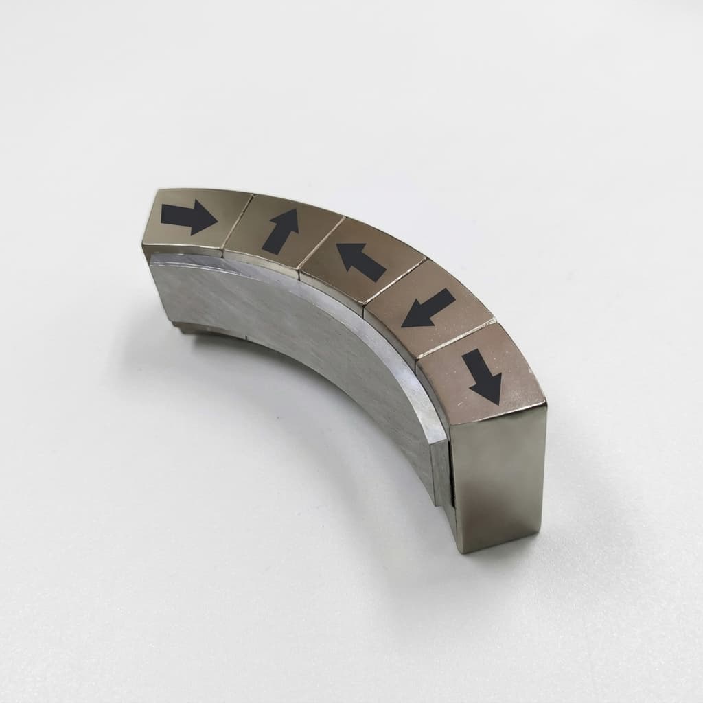
A segmented axial Halbach sequence can use 90° magnetization steps (4 blocks per pole-pair) or 45° steps (8 blocks per pole-pair). The intended sequence rotates between axial and circumferential components. More orientations approximate a continuous distribution more closely, but also add fixtures, bondlines, and polarity inspection points.
2.2 Symmetrical Flux Closure vs. Yokeless Rotors
In a single-stator dual-rotor axial flux machine, two distinct magnetic flux circulation schemes exist:
- Opposite working-face poles across the stator: A North working face on Rotor 1 faces a South working face on Rotor 2. The useful axial field crosses the winding region. The Halbach sequence on each disc must concentrate its strong side inward; copying an orientation drawing without mirroring its coordinate convention can produce the wrong working face.
- Like working-face poles across the stator: This arrangement changes the flux path and may suppress the useful axial field at the central plane. It is not interchangeable with the opposite-pole coreless design. If the proposed motor uses iron segments or another return path, require a separate field and force model rather than transferring coreless assumptions.
A Halbach layout may reduce the electromagnetic need for a steel return yoke. It does not eliminate the structural carrier or guarantee zero backside flux. Ask for inner-edge, outer-edge, and backside leakage maps as well as the winding-plane map, especially near encoders, brakes, and conductive housings.
3. Rotor Disc Mechanical Construction & Back-Plate Materials
In high-torque density axial-flux machines, the rotor disc does not merely hold the magnets—it must resist enormous mechanical and magnetic stresses.
Under operation, the rotor discs experience:
- Axial Magnetic Loads: Mutual rotor attraction can bend the plates inward. The illustrative force calculation in Section 5 shows the order of magnitude for one assumed field and annulus. Deflection must be evaluated against the minimum hot running clearance, not against diameter alone.
- Centrifugal and Transient Loads: The bond, pockets, and any retaining rim must support the tiles at maximum speed, acceleration, and specified fault conditions. Quote the overspeed qualification separately from normal operation.
- Parasitic Eddy Current Heating: Rotor-frame time-varying fields can induce currents in conductive carriers. Backside attenuation reduces one source of exposure but does not establish the completed rotor's loss or temperature.
The following engineering decision matrix compares the primary rotor structural back-plate materials evaluated during OEM sourcing:
| Structural Back-Plate Material | Main Sourcing Advantage | Mechanical Design Check | Electrical / Thermal Check | Evidence to Request | Main Qualification Risk |
|---|---|---|---|---|---|
| Quasi-isotropic CFRP | Low mass with tailored stiffness | Layup-dependent bending, hub joints, and delamination | Carbon fibers conduct; losses are anisotropic and resin temperature limits matter | Layup specification, cured-laminate data, and joint tests | Treating fiber strength as finished-disc strength |
| Titanium Grade 5 | Strength and higher resistivity than aluminum | Plate thickness, fatigue, and magnet retention | Higher resistivity can help, but rotor loss still needs analysis | Material certificate, deflection model, and machining plan | Cost, heat rejection, and joint details |
| Aluminum 7075-T6 | High strength and established machining routes | Elastic deflection and stress-corrosion environment | Conductive plate may develop eddy losses | Temper certificate, assembled geometry, and loss model | Assuming higher yield strength means much higher elastic stiffness |
| Aluminum 6061-T6 | Availability and machining economy | Thickness, support radius, and yield margin | Conductive plate; assess rotor-frame harmonic exposure | Same structural and thermal evidence as other metals | Rejecting or approving it from alloy name alone |
| Low-carbon steel | Stiff carrier that can also provide a flux return path | Mass, inertia, saturation, and retention | Magnetic and eddy effects depend on field and construction | Coupled magnetic/structural comparison | Applying non-magnetic-carrier assumptions to a magnetic yoke |
| Glass-filled PEEK | Electrical insulation and low mass | Creep, fiber direction, thermal expansion, and insert joints | Polymer temperature capability is grade- and load-dependent | Grade-specific data and hot-load creep tests | Long-term clearance loss under sustained attraction |
Engineering Takeaway on Carrier Selection
Treat this table as a comparison of qualification questions, not a material approval list. Bending stiffness depends on geometry and elastic modulus; a stronger aluminum alloy does not automatically permit a thinner plate at the same deflection. CFRP requires laminate-level properties, not a generic tensile yield value. Compare carriers at the same allowable hot deflection and assembled inertia.
The fundamental electrical frequency is f_e = pn/60, where p is pole pairs and n is speed in RPM. A synchronous fundamental field is approximately stationary relative to the rotor. Rotor heating depends on the harmonics that move relative to it, PWM ripple, and their amplitudes—not a universal 400 Hz or 1,000 Hz rejection threshold. If the carrier is undecided, request a comparison of candidate rotor constructions using the same gap and duty-cycle inputs.
4. NdFeB Magnet Segmentation & Demagnetization Mitigation
A common misconception among motor sourcing teams is that removing the stator iron core eliminates all high-frequency rotor heating. In reality, in a slotless or coreless axial flux motor:
- Slotting Harmonics Are Removed, but Winding Harmonics Remain: A fully ironless winding removes tooth-related cogging. Its spatial current distribution can still produce magnetomotive force (MMF) harmonics, depending on the winding layout and drive currents. Identify their frequencies in the rotor reference frame before predicting loss.
- Inverter PWM Carrier Sidebands: PWM creates current and field components that vary relative to the rotor. Their amplitudes depend on the inverter, winding inductance, and control strategy. Specify the actual carrier frequency and ripple spectrum rather than treating the switching frequency alone as a loss prediction.
Use the supplier’s electrical resistivity rather than a universal grade value. For an illustrative NdFeB resistivity range (ρ_e ≈ 140 to 180 µΩ·cm), the material remains conductive. The skin depth δ of high-frequency fields in NdFeB is given by:
δ = sqrt(ρ_e / (π · f · µ_0 · µ_r))Here µ_0 = 4π × 10⁻⁷ H/m is the vacuum permeability, f is the rotor-frame excitation frequency in hertz, ρ_e is in Ω m, and µ_r is relative permeability. For an illustrative resistivity of 150 µΩ·cm and µ_r = 1.05 at 50 kHz, this expression gives δ ≈ 2.7 mm. It describes field penetration in a simplified conductor, not an operating temperature or an automatic magnet segment size. Actual heating also depends on ripple amplitude, tile geometry, electrical contact between tiles, and heat removal.
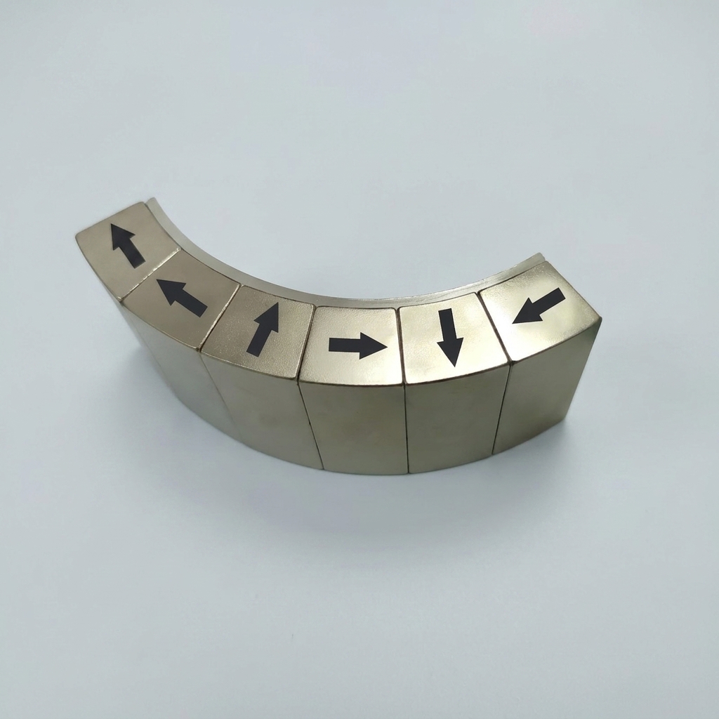
Illustrative curved magnet segment assembly with direction markings. This image is not a disc-pair inspection record and does not verify electrical isolation or the specified Halbach sequence.
The following matrix separates loss-control decisions from coercivity and production cost. None of these options has a universal frequency limit, loss-reduction percentage, or price multiplier.
| Magnet Configuration | Intended Benefit | What It Does Not Establish | Required Supplier Evidence | Cost Driver | Acceptance Focus |
|---|---|---|---|---|---|
| Solid sintered NdFeB tile | Fewer parts and bondlines | Suitability for the proposed inverter spectrum | Rotor-loss model and thermal test plan | Tile size, grade, tooling, and yield | Hot demagnetization margin and retention |
| Circumferentially split NdFeB | Interrupt selected eddy-current paths | A fixed reduction without a geometry-specific model | Segmented-versus-solid comparison with equal magnet volume | More cuts, handling, and insulation | Electrical isolation after assembly |
| Radially and circumferentially split tiles | Interrupt loops in more than one direction | A guaranteed thermal benefit after extra bondlines reduce fill factor | Three-dimensional loss distribution and tolerance stack | Fixtures, tile count, and inspection effort | Position, insulation, and bondline consistency |
| Grain-boundary-diffused NdFeB | Improve coercivity for an appropriate grade and section | Eddy-current reduction solely from the diffusion process | Temperature-dependent demagnetization curves and process coverage | Grade, diffusion process, and part thickness | Coercivity throughout the specified section |
| Sm2Co17 | Candidate for demanding temperature or stability requirements | Immunity to eddy heating or an assembly temperature rating | Grade curves, brittleness allowance, and bond compatibility | Material, grinding, handling, and scrap | Chipping, retention, and hot working point |
| Thin insulated magnet stacks | Shorter conductive paths where the loss model supports them | Universal aerospace suitability or a specific percentage saving | Stack packing factor and electrical/thermal validation | Many layers, coating, bonding, and assembly time | Insulation survival and reduced magnetic fill |
Engineering Rule of Thumb for RFQ Specifications
Ask suppliers to quote a baseline and one segmented alternative against the same operating spectrum and temperature limit. Give pole count, speed range, inverter carrier frequency, current ripple or measured current spectrum, duty cycle, and cooling boundary conditions. Request predicted rotor losses, the modeling assumptions, and a plan for checking hot flux retention. Define the segment directions on a drawing rather than saying only “three splits per pole.”
Do not select a UH or SH suffix solely from the winding temperature. The rotor magnet temperature, external opposing field, permeance coefficient, and supplier-specific demagnetization curves determine the working-point margin. A supplier should explain how the chosen coating, adhesive, and carrier jointly limit the assembly temperature.
5. Multi-Kilonewton Axial Attraction Balancing & Tolerance Budgets
Rotor-to-rotor attraction, disc deflection, and minimum running clearance belong in the same sourcing specification. They should not be collapsed into a single “balanced axial force” claim.
5.1 Rotor Clamping and the Actual Load Path
A fully ironless stator does not provide the high-permeability attraction target of an iron-cored stator. With both rotors locked to one rigid assembly, a small axial translation of the non-magnetic PCB changes the two clearances but not the magnet-to-magnet separation. It therefore does not, by itself, prove a specified net magnetic thrust on the bearings. Separately supported rotors, magnetic stator material, or nearby ferromagnetic housings require their own force and load-path analysis.
For a rough rotor-pair attraction screen, assume a uniform axial field, negligible tangential field, and active annular area A:
F_screen ≈ B_z² · A / (2 · µ_0)For an illustrative inner diameter of 100 mm and outer diameter of 160 mm:
A = (π/4) · (0.160² − 0.100²) ≈ 0.01225 m²If the assumed uniform field is 0.95 T, the screen gives approximately 4.4 kN. This is calculated from selected inputs, not a measured rotor load. For a nonuniform field, integrate Maxwell stress using the local normal and tangential field components; the square of an average field is not generally the average of the squared field.
The carrier and hub must sustain their local magnetic loads even if internal attraction produces little net external thrust on the complete rotor assembly. Ask the supplier to identify which components close that force path. Require the structural model to include support radius, bolt or hub constraints, centrifugal loading, temperature, and plausible assembly errors. Hong et al.'s iron-cored machine offers structural context, not a numerical bearing-load rule for this coreless example.
A useful clearance budget records the cold nominal gap and the maximum reduction caused by each contribution:
Per-side operating clearance worksheet:
- Cold nominal clearance at the specified datum
- Installed axial runout and magnet-face waviness
- Carrier deflection under the modeled magnetic load
- Bearing end-play, shaft/hub motion, and relative tilt
- Differential thermal expansion and transient movement
- Remaining minimum clearance and agreed measurement uncertainty
Specify the datum, support state, temperature, and measurement radius for each tolerance. Avoid double-counting the same motion in both a runout limit and a stack allowance. For example, 0.05° tilt corresponds to about 0.070 mm axial displacement at an 80 mm radius; that can consume a meaningful part of the available clearance even when individual machined faces pass inspection.
5.2 Dynamic Balancing Standards (ISO 21940-11)
Use ISO 21940-11:2016, including applicable amendments, for rotors with rigid behavior. It covers residual unbalance, correction-plane selection, allocation, and balancing errors. A thin disc does not automatically require two-plane correction; select the method from the assembled rotor behavior and relevant couple unbalance. Flexible-rotor behavior requires a different procedure.
- Agree the grade and reference speed: G2.5 and G1.0 are possible contractual targets, not universal requirements for robotics or aircraft. State permissible residual unbalance in the allocated correction planes and the final assembly condition. Using
Ginmm/s,e_per = G/ωin millimeters, ore_per = 1000G/ωin micrometers, withω = 2π n/60. - Check a reproducible example: At
3,000 RPMand G2.5,e_per ≈ 7.96 µm. For a1 kgrotor, the corresponding total permissible residual unbalance is approximately7.96 g mmbefore allocation to correction planes. This arithmetic does not select the correct grade for a machine. - Balance the delivered configuration: Final magnet bonding, curing, coatings, and retention hardware affect the result. Define permitted correction zones, correction material retention, mounting repeatability, and the report format. Balance acceptance does not replace overspeed, bearing, or rotor-dynamic validation.
6. Factory Testing & Quality Inspection Protocols
Use the following four-part qualification framework to make supplier offers comparable. Numerical pass/fail limits must come from the motor requirements and a pilot-lot capability review; the procedure does not guarantee zero defects.
Protocol 1: Working-Plane Hall Mapping
- Inspection setup: Record probe calibration, uncertainty, temperature, coordinate axes, and distance from the magnet face. Identify whether the scan covers one rotor, the matched pair, or a model validated against separate scans.
- Scan trajectory: Specify concentric tracks over the active radial span, angular sampling, and the copper-plane locations. For the
4.0 mmsymmetric example, the center plane is2.0 mmfrom each magnet face. If the fixture cannot scan the assembled gap, agree a correlated single-disc method. - Data deliverables: Preserve signed raw field data, pole-to-pole variation, fundamental amplitude, phase relative to the mechanical datum, and the harmonic bandwidth. Define whether amplitudes are peak or RMS before comparing reports.
For harmonic amplitudes defined consistently, a useful distortion metric is:
THD_B = sqrt(sum[n = 2 to N](B_zn²)) / B_z1 × 100%Agree N, sampling resolution, and the acceptable limit. Field THD alone does not establish torque ripple: winding distribution, current control, and mechanical effects also matter. Require phase consistency across both discs so that a correct individual map cannot conceal an incorrectly clocked pair.
Protocol 2: Installed Runout and Geometry
Measure the mounting interface, magnet surface, and adjacent segment step height against named datums. State whether the rotor is free, mounted to a master arbor, or installed with the final hub torque. Runout on a precision fixture can differ from the installed assembly. Agree the measurement radius, allowable variation, and inspection uncertainty from the clearance budget rather than copying a generic micrometer limit.
Include both magnet-face flatness and axial stack variation where they can reduce the gap. Record corrective rework and reinspection. A CMM report establishes geometry; it cannot verify a magnetization vector or magnetic grade.
Protocol 3: Bond and Retention Qualification
Select the adhesive by substrate, coating, bondline, cure schedule, service temperature, and load direction. An anaerobic retaining compound and a two-part structural epoxy are different joining systems; neither name establishes suitability for bonding magnet tiles to an open carrier face.
Require representative coated-magnet/carrier coupons and agreed shear, peel, thermal-cycle, and environmental tests. Report test temperature, aging, specimen preparation, failure mode, and scatter. Generic room-temperature datasheet lap-shear strength is not an allowable design stress at the hot rotor condition. Use non-destructive inspection only where the method has been demonstrated to detect the relevant bond defect. Qualify any retaining rim or cover separately for maximum speed and fault loads.
Protocol 4: Back-EMF, Drive, and Thermal Acceptance
For matched kits, define the reference stator, winding connection, temperature, speed, voltage convention, and instrumentation. A line-to-line RMS voltage constant cannot be compared directly with a phase peak value. Check waveform harmonics and phase alignment, then validate loaded behavior at agreed operating points. Continuous torque requires thermal stabilization under stated cooling conditions; a short peak test cannot establish it.
Request synchronized current, voltage, speed, and temperature records with sampling bandwidth sufficient for the claimed phenomenon. Petersen and Severson's AMDC control and sensing platform paper is an instrumentation reference for electric-drive development, not evidence of Halbach torque gains. The RFQ should specify the required test channels and calibration regardless of which control platform the supplier uses. Where rotor temperature is not directly measured, require the estimation method and its validation limits.
7. The B2B Axial Flux Halbach Rotor Procurement & RFQ Checklist
To obtain an accurate, production-ready engineering quotation without protracted redesign cycles, provide the following parameters in your RFQ package:
- Motor Geometry & Dimensional Envelope: Specify rotor outer diameter (
D_out), inner diameter (D_in), maximum permissible axial stack length, and central bore/shaft interface geometry. - Coreless Stator & Air-Gap Definition: Define the exact stator substrate thickness (
t_stator), mechanical clearance on Rotor 1 (g_1), mechanical clearance on Rotor 2 (g_2), and target magnetic gap (g_m = g_1 + t_stator + g_2). - Working Flux Density Requirement: Define the required fundamental field at named copper planes, peak or RMS convention, permitted variation, harmonic bandwidth, and matched-pair measurement method. Set the target from the winding and torque model.
- Magnetic Material & Thermal Grade: State candidate NdFeB or Sm2Co17 grades, rotor temperature range, opposing-field conditions, and required temperature-dependent demagnetization curves. Keep winding and magnet temperatures separate.
- Magnet Segmentation & Insulation: Provide a dimensioned cut pattern, electrical isolation method, bondline tolerance, and insulation verification procedure. Require a baseline-versus-segmented loss comparison with the specified drive spectrum.
- Rotor Carrier & Retention: Identify candidate materials, mounting constraints, maximum permitted hot deflection, maximum speed, fault loads, coating system, and retention concept.
- Runout & Geometric Tolerances: Specify datums, installed TIR, face flatness, segment step height, pole clocking tolerance, and measurement uncertainty based on the operating clearance budget.
- Balance Acceptance: Agree ISO 21940-11 where applicable, the balance grade, reference speed, permissible residual unbalance, correction planes, and final delivered configuration. Include the test report and permitted correction zones.
- Environmental Compatibility: Define corrosion, humidity, coolant, and thermal-cycle exposure. Agree a coating and qualification test for the actual environment; a salt-spray duration alone does not predict service life.
- Quality Deliverables & Commercial Scope: Require serialized Hall maps, geometry and balance records, magnet-lot traceability, and bond-qualification evidence. Separate prototype tooling, non-recurring engineering, unit price, inspection cost, minimum order quantity, lead time, delivery terms, and change-control responsibilities.
8. Frequently Asked Questions (FAQ)
Why use an axial flux Halbach array instead of a radial flux brushless rotor for robot joints?
A large active diameter can provide useful torque in a short axial package. A coreless winding removes tooth-related cogging, while a Halbach array may improve the useful field for an acceptable magnet and carrier mass. The advantage is conditional: compare thermal limits, rotor inertia, available radial space, winding manufacture, and total cost with a radial-flux alternative. For equal uniform shear stress and a fixed inner/outer radius ratio, annular torque scales with the cube of diameter; other constraints can change that comparison.
Can we use standard 6061-T6 aluminum for the rotor back-plate to save machining costs?
Possibly. Its acceptability depends on plate thickness, support geometry, stress, hot deflection, and rotor harmonic exposure. The elastic moduli of 6061-T6 and 7075-T6 are similar, so changing to 7075 does not by itself solve an elastic deflection problem. Higher-strength alloys can improve yield margin, while titanium or a qualified composite may offer other benefits at a different cost. Request a same-envelope structural and loss comparison rather than accepting a blanket alloy prohibition.
How do you assemble two high-strength Halbach rotor discs without mechanical damage or personal injury?
Use a qualified assembly fixture that restrains translation and tilt and controls the approach under the calculated magnetic load. Do not bring magnetized discs together by hand. Specify fixture load rating, positive stops, controlled separation for rework, and protection against brittle magnet fragments. Confirm the magnetic behavior of tooling materials; a generic stainless-steel label does not establish that a fixture is non-magnetic. The supplier's documented assembly method should match the rotor diameter and attraction level.
Why does our motor experience excessive bearing wear even though the stator has no iron teeth?
Investigate the load path before attributing wear to magnetic gap asymmetry. Relevant causes include transmitted rotor attraction, preload errors, end-play, misalignment, imbalance, thermal growth, external loads, and contamination. In a fully coreless design, shifting the PCB inside a fixed rotor pair does not create the iron-stator attraction mechanism of a cored machine. Measure installed runout and bearing condition, identify which member moves, and reconcile the measured loads with the mechanical and magnetic models.
What is the maximum practical temperature for an axial flux Halbach rotor using NdFeB?
There is no assembly-wide temperature rating from a grade suffix alone. Obtain the actual supplier's demagnetization curves at the intended rotor temperature and evaluate the magnet working point under the maximum opposing field. Coating, adhesive, carrier, insulation, and retention hardware may impose a lower limit than the magnet. Sm2Co17 can be considered where NdFeB does not meet the required margin, but it still needs grade-specific magnetic, mechanical, and joint qualification. Do not use the winding temperature as a substitute for rotor temperature.
How does magnet segment count affect axial flux rotor manufacturing cost?
Distinguish the Halbach orientation sequence from extra electrically isolated cuts within each orientation. Four blocks per pole-pair use four directed magnetization vectors at 90° steps; eight blocks use eight directed vectors at 45° steps. Opposite polarities may share a physical orientation axis, but their magnetization directions differ. More pieces generally add handling, fixtures, bondlines, and inspection, while the resulting field gain depends on geometry. Ask for itemized tooling, material, assembly, inspection, and scrap allowances; neither a fixed percentage flux gain nor a fixed cost multiplier is assumed here.
9. Conclusion & Sourcing Next Steps
Dual-rotor Halbach arrays are worth comparing when a coreless axial-flux motor needs useful working-plane field in a thin package. Select the topology from a coupled electromagnetic, structural, thermal, and manufacturing comparison. Removing tooth-related cogging does not guarantee low torque ripple, high continuous torque, or favorable system efficiency.
When evaluating supplier proposals, reject quotations based solely on magnet material weight or surface Gauss ratings. Demand documented validation of air-gap flux density profiles at the stator copper plane, structural disc deflection simulations, and serialized dynamic balancing certifications.
Ready to Validate Your Axial Flux Rotor Design?
Use these product and application pages to frame a design-review request. Share the RFQ checklist with candidate suppliers and ask them to identify any assumptions, exclusions, or unvalidated requirements before quoting:
- Explore Product Capabilities: Review our dedicated Halbach Rotors portfolio and Custom Halbach Assemblies.
- Application Solutions: Discover our direct-drive integration expertise in Robotics Actuators and BLDC Motors & Generators.
- Request a Design Review: Submit your CAD drawings, air-gap dimensions, and electromagnetic targets to our technical team via our Direct Engineering Contact Portal.
References & Authoritative Sources
-
Hong, D.-K., Park, J.-H., & Jeong, Y.-H. (2024 issue; published December 20, 2023).
Comprehensive Analysis of Dual-Rotor Yokeless Axial-Flux Motor with Surface-Mounted and Halbach Permanent Magnet Array for Urban Air Mobility.
Energies, 17(1), Article 30.
DOI: 10.3390/en17010030
Scope: an iron-cored segmented-armature AFPM machine, prototype validation, structural analysis, and a proposed Halbach design. Its results do not establish coreless PCB-stator performance or a universal gap-offset bearing load. -
Petersen, N. P., & Severson, E. L. (2023).
AMDC: Open-Source Control and Sensing Platform for Advanced Electric Motor Drives.
2023 IEEE International Electric Machines & Drives Conference (IEMDC), pp. 1–7.
DOI: 10.1109/IEMDC55163.2023.10238914
Scope: electric-drive control and sensing instrumentation, relevant to specifying a test data-acquisition setup. It is not a Halbach rotor comparison or a source for percentage torque gains. -
ISO 21940-11:2016, with applicable amendments.
Mechanical vibration — Rotor balancing — Part 11: Procedures and tolerances for rotors with rigid behaviour.
Source: ISO 21940-11 official catalogue
Scope: rigid-rotor residual unbalance, correction planes, allocation, and balancing errors. Agree grade and operating conditions in the contract; the catalogue does not establish a universal robotics or aircraft grade.
Source identities and scope checked November 8, 2026. The calculations above are reproducible screening examples; no original motor test results or customer performance claims are presented.
Author

More Posts
Halbach Array Magnetic Couplings: Torque Density, Containment Shell Eddy Losses, and OEM Sourcing Guide
Compare Halbach array magnetic couplings by torque density, containment shell eddy losses, and slip limits. Use an OEM RFQ checklist to request a design review.
Preventing Thermal Demagnetization in Halbach Arrays: Grade Selection and GBD Guide
Guide to Halbach array thermal demagnetization, magnet grade selection, GBD limits, supplier validation, and RFQ checks for engineering teams.
Halbach Array Segment Count: 4 vs 8 vs 16 Blocks (Cost & Performance)
Compare Halbach array segment counts across 4, 8, and 16 blocks: flux, ripple, eddy-current risk, cost drivers, QC checks, and RFQ guidance.